Introduction to Flyback Diodes
Flyback diodes, also known as snubber diodes or freewheeling diodes, are an essential component in relay circuits. They play a crucial role in preventing electrical noise and protecting sensitive components from voltage spikes that occur when a relay is switched off. In this article, we will dive deep into the world of flyback diodes, exploring their working principle, importance, and practical applications in relay circuits.
What are Flyback Diodes?
A flyback diode is a simple yet effective device that consists of a single diode connected in parallel with an inductive load, such as a relay coil. The diode is placed in reverse bias, meaning that it does not conduct current during normal operation when the relay is energized. However, when the relay is switched off, the diode provides a path for the stored energy in the coil to dissipate safely.
The Need for Flyback Diodes in Relay Circuits
Relays are electromechanical switches that use an electromagnet to control the switching of electrical contacts. When a relay is energized, current flows through the coil, creating a magnetic field that attracts the armature and closes the contacts. However, when the relay is de-energized, the magnetic field collapses rapidly, inducing a high-voltage spike across the coil. This voltage spike, known as the back electromotive force (back EMF), can be several times higher than the original supply voltage.
The back EMF generated by the collapsing magnetic field can cause several problems in a circuit:
-
Damage to sensitive components: The high-voltage spike can exceed the voltage rating of sensitive components such as transistors, integrated circuits, and microcontrollers, causing permanent damage.
-
Electromagnetic interference (EMI): The rapid change in current during the switching process can generate high-frequency noise that can interfere with nearby electronic devices and communication systems.
-
Arcing and contact wear: The voltage spike can cause arcing across the relay contacts, leading to premature wear and reduced lifespan of the relay.
To mitigate these issues, flyback diodes are employed in relay circuits.
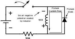
How Flyback Diodes Work
When a relay is energized, the flyback diode is reverse-biased and does not conduct current. However, when the relay is switched off, the collapsing magnetic field induces a reverse voltage across the coil. At this point, the flyback diode becomes forward-biased and provides a low-resistance path for the stored energy in the coil to dissipate.
The flyback diode effectively “short-circuits” the induced voltage, limiting its magnitude to the forward voltage drop of the diode (typically around 0.7V for a silicon diode). This prevents the high-voltage spike from reaching and damaging sensitive components in the circuit.
The energy stored in the coil is dissipated as heat through the diode, and the current gradually decays to zero. The time taken for the current to decay depends on the inductance of the coil and the forward resistance of the diode.
Selecting the Right Flyback Diode
Choosing the appropriate flyback diode is crucial for effective protection and reliable operation of the relay circuit. Here are some key factors to consider when selecting a flyback diode:
-
Reverse voltage rating: The diode must have a reverse voltage rating higher than the maximum voltage expected across the relay coil. A good rule of thumb is to choose a diode with a reverse voltage rating at least twice the supply voltage.
-
Forward current rating: The diode should be able to handle the peak current flowing through the relay coil during the switching process. The forward current rating of the diode must be higher than the maximum coil current.
-
Recovery time: The diode’s recovery time, which is the time taken for the diode to regain its blocking capability after conducting, should be fast enough to prevent any significant voltage spikes from reaching the sensitive components.
-
Package size: The diode package should be chosen based on the available space and the required power dissipation. Surface-mount diodes are commonly used in modern electronic circuits due to their small size and low profile.
Some popular choices for flyback diodes include the 1N4001 series (1N4001-1N4007) for general-purpose applications and the 1N5817 or Schottky diodes for faster recovery times and lower forward voltage drops.

Practical Applications of Flyback Diodes
Flyback diodes find extensive use in various applications where relays are employed for switching purposes. Some common applications include:
-
Automotive electronics: In automotive systems, relays are used for controlling various loads such as headlights, horns, and power windows. Flyback diodes are essential to protect the sensitive electronic control units (ECUs) from voltage spikes generated during relay switching.
-
Industrial control systems: Relays are widely used in industrial control systems for switching high-power loads such as motors, solenoids, and contactors. Flyback diodes help in reducing electromagnetic interference and extending the life of the relays by minimizing arcing and contact wear.
-
Home automation: In home automation systems, relays are used for controlling lighting, appliances, and HVAC systems. Flyback diodes ensure the reliable operation of the control circuitry and prevent interference with other electronic devices in the home.
-
Telecommunications: Relays are used in telecommunications equipment for switching signals and controlling various functions. Flyback diodes are crucial for protecting sensitive electronic components and maintaining signal integrity.

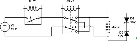
Implementing Flyback Diodes in Relay Circuits
Implementing a flyback diode in a relay circuit is a straightforward process. The diode is connected in parallel with the relay coil, with the cathode (banded end) connected to the positive supply and the anode connected to the negative supply.
Here’s an example schematic showing the connection of a flyback diode in a relay circuit:
            +--------+
            |        |
            |     Relay Coil
            |        |
            +---||---+
                ||
                ||
                ||
           Flyback Diode
                ||
                ||
                ||
            +---||---+
            |        |
            |        |
           GND      GND
It is important to ensure that the diode is connected with the correct polarity. If the diode is connected in the wrong direction, it will conduct during normal operation and prevent the relay from functioning properly.
When selecting the flyback diode, it is recommended to choose a diode with a reverse voltage rating at least twice the supply voltage and a forward current rating higher than the maximum coil current. For example, if the relay coil is rated for 12V and draws a maximum current of 500mA, a 1N4007 diode (reverse voltage rating: 1000V, forward current rating: 1A) would be a suitable choice.
Testing and Troubleshooting
After implementing the flyback diode in the relay circuit, it is essential to test the circuit to ensure proper operation and protection. Here are some steps to follow:
-
Visual inspection: Verify that the diode is connected with the correct polarity and that there are no shorts or open circuits in the wiring.
-
Resistance check: Using a multimeter, measure the resistance across the relay coil with the diode in place. The resistance should be high (several kΩ or more) in one direction and low (a few Ω) in the other direction, indicating that the diode is functioning correctly.
-
Voltage measurement: With the relay energized, measure the voltage across the diode using a multimeter. The voltage should be close to zero, as the diode is reverse-biased. When the relay is de-energized, the voltage across the diode should be limited to the forward voltage drop (around 0.7V for a silicon diode).
-
Oscilloscope analysis: For more advanced troubleshooting, an oscilloscope can be used to observe the voltage waveform across the relay coil during the switching process. The flyback diode should effectively suppress any high-voltage spikes, resulting in a clean and smooth waveform.
If the circuit is not functioning as expected or if voltage spikes are still present, check the following:
-
Diode polarity: Ensure that the diode is connected with the correct polarity (cathode to positive, anode to negative).
-
Diode ratings: Verify that the selected diode has appropriate voltage and current ratings for the specific relay and supply voltage.
-
Wiring connections: Check for loose or faulty connections in the circuit, as they can cause intermittent operation or introduce noise.
-
Relay condition: Inspect the relay contacts for signs of wear, pitting, or contamination. A damaged or worn-out relay can cause abnormal behavior and may require replacement.
Best Practices and Tips
To ensure optimal performance and reliability of relay circuits with flyback diodes, consider the following best practices and tips:
-
Keep the diode close to the relay: Mount the flyback diode as close to the relay coil as possible to minimize the loop area and reduce the effect of stray inductance.
-
Use a heatsink if necessary: In applications with high switching frequencies or large coil currents, the flyback diode may dissipate significant power. In such cases, consider using a heatsink to prevent overheating and ensure reliable operation.
-
Consider using a TVS diode: For additional protection against voltage transients, a transient voltage suppressor (TVS) diode can be used in conjunction with the flyback diode. TVS diodes offer faster response times and can clamp the voltage to a specific level.
-
Maintain proper grounding: Ensure that the circuit has a solid and low-impedance ground connection to minimize ground loops and reduce the impact of electromagnetic interference.
-
Use appropriate wiring techniques: Use shielded cables or twisted pair wiring to minimize the coupling of noise from the relay switching to other parts of the circuit. Keep the wiring as short as possible and avoid running sensitive signal lines near the relay.
-
Consider the environment: When designing relay circuits for harsh environments, such as those with high temperatures, vibration, or moisture, choose components (including flyback diodes) that are rated for the specific conditions to ensure reliable operation.
Conclusion
Flyback diodes are a simple yet essential component in relay circuits, providing critical protection against voltage spikes and electrical noise. By understanding the working principle and importance of flyback diodes, engineers and hobbyists can design more reliable and robust relay-based systems.
When selecting and implementing flyback diodes, it is crucial to consider factors such as voltage and current ratings, recovery time, and package size. Following best practices and tips, such as keeping the diode close to the relay, using appropriate wiring techniques, and maintaining proper grounding, can further enhance the performance and reliability of the circuit.
By incorporating flyback diodes in relay circuits, designers can mitigate the risks of component damage, electromagnetic interference, and premature relay failure, ultimately leading to more efficient and dependable systems across various applications, from automotive electronics to industrial control systems and beyond.
Frequently Asked Questions (FAQ)
-
What is the purpose of a flyback diode in a relay circuit?
A flyback diode is used to protect sensitive components and reduce electrical noise in a relay circuit by providing a path for the stored energy in the relay coil to dissipate safely when the relay is switched off. -
How does a flyback diode work?
When the relay is de-energized, the collapsing magnetic field induces a high-voltage spike across the coil. The flyback diode becomes forward-biased and conducts, effectively “short-circuiting” the induced voltage and limiting its magnitude to the forward voltage drop of the diode. -
What are the key factors to consider when selecting a flyback diode?
When choosing a flyback diode, consider the following factors: reverse voltage rating (should be at least twice the supply voltage), forward current rating (higher than the maximum coil current), recovery time (fast enough to prevent voltage spikes), and package size (based on available space and power dissipation requirements). -
Can a flyback diode be connected in the wrong polarity?
Yes, if a flyback diode is connected in the wrong polarity (anode to positive, cathode to negative), it will conduct during normal operation and prevent the relay from functioning properly. Always ensure that the diode is connected with the correct polarity (cathode to positive, anode to negative). -
What are some best practices for implementing flyback diodes in relay circuits?
Some best practices include: mounting the diode close to the relay coil to minimize loop area and stray inductance, using a heatsink for high-power applications, considering a TVS diode for additional transient protection, maintaining proper grounding, using appropriate wiring techniques (shielded cables or twisted pairs), and selecting components rated for the specific environmental conditions.
Leave a Reply