Introduction to Rigid-Flex PCBs
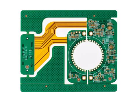
Rigid-flex PCBs are a hybrid of rigid and flexible printed circuit boards that offer unique advantages in terms of space savings, weight reduction, and enhanced reliability. These PCBs consist of rigid and flexible layers laminated together, allowing for three-dimensional packaging and improved electrical performance. Rigid-flex PCBs find applications in various industries, including aerospace, medical devices, automotive, and consumer electronics.
Advantages of Rigid-Flex PCBs
- Space savings and miniaturization
- Reduced weight
- Enhanced reliability and durability
- Improved electrical performance
- Three-dimensional packaging capabilities
Structural Integrity Challenges in Rigid-Flex PCB Design
Designing rigid-flex PCBs comes with its own set of challenges, particularly in ensuring structural integrity. The combination of rigid and flexible materials, along with the dynamic stresses experienced during flexing, can lead to various issues if not properly addressed.
Stress Concentration Points
One of the primary challenges in rigid-flex PCB design is managing stress concentration points. These points occur at the transition between the rigid and flexible sections of the PCB, where the material properties change abruptly. Proper design techniques must be employed to minimize stress concentrations and prevent premature failure.
Techniques to Mitigate Stress Concentration
- Gradual transition between rigid and flexible sections
- Use of strain relief features
- Proper placement of components and traces
- Selection of appropriate materials and adhesives
Flexing Fatigue
Flexing fatigue is another critical challenge in rigid-flex PCB design. Repeated flexing of the PCB can lead to material degradation and eventual failure if not properly addressed. Designers must consider the expected flexing cycles and design the PCB accordingly.
Factors Affecting Flexing Fatigue
- Number of flexing cycles
- Flexing radius and angle
- Material properties and thickness
- Environmental conditions (temperature, humidity)
Material Selection and Compatibility
Proper material selection is crucial for ensuring structural integrity in rigid-flex PCBs. The materials used for the rigid and flexible sections must be compatible and able to withstand the stresses encountered during manufacturing and operation.
Key Considerations for Material Selection
- Mechanical properties (strength, flexibility, CTE)
- Electrical properties (dielectric constant, loss tangent)
- Thermal properties (glass transition temperature, thermal conductivity)
- Adhesion and bonding characteristics
Design Guidelines for Structural Integrity
To ensure structural integrity in rigid-flex PCBs, designers should follow certain guidelines and best practices.
Proper Layer Stack-up
The layer stack-up of a rigid-flex PCB plays a critical role in its structural integrity. Designers should consider the following factors when defining the layer stack-up:
- Number and placement of rigid and flexible layers
- Thickness and material properties of each layer
- Adhesive selection and thickness
- Copper weight and distribution
Mechanical Support and Reinforcement
Providing adequate mechanical support and reinforcement is essential for maintaining structural integrity in rigid-flex PCBs. This can be achieved through various techniques, such as:
- Use of stiffeners and backing materials
- Selective reinforcement of high-stress areas
- Proper mounting and enclosure design
Design for Manufacturability (DFM)
Designing rigid-flex PCBs with manufacturability in mind is crucial for ensuring structural integrity. DFM guidelines help minimize manufacturing-related issues and improve overall reliability.
Key DFM Considerations
- Minimum bend radius and bend angle
- Clearance and spacing requirements
- Copper balancing and symmetry
- Panelization and depanelization techniques

Simulation and Testing
Simulation and testing play a vital role in validating the structural integrity of rigid-flex PCBs before manufacturing.
Finite Element Analysis (FEA)
FEA is a powerful tool for simulating the mechanical behavior of rigid-flex PCBs under various loading conditions. It helps identify potential stress concentration points, flexing fatigue issues, and other structural weaknesses.
FEA Simulation Scenarios
- Static stress analysis
- Dynamic flexing analysis
- Thermal stress analysis
- Vibration analysis
Physical Testing
Physical testing is essential to validate the simulation results and ensure the structural integrity of the manufactured rigid-flex PCBs. Common physical tests include:
- Bend testing
- Thermal cycling
- Shock and vibration testing
- Microsectioning and cross-sectional analysis
Case Studies and Real-World Examples
To illustrate the challenges and solutions related to structural integrity in rigid-flex PCBs, let’s explore some case studies and real-world examples.
Case Study 1: Aerospace Application
In this case study, a rigid-flex PCB was designed for an aerospace application that required high reliability and durability under extreme environmental conditions. The design team faced challenges in managing stress concentration points and ensuring adequate flexing fatigue resistance.
Solution
- Gradual transition between rigid and flexible sections
- Use of high-performance materials (polyimide, high-Tg epoxy)
- Selective reinforcement of high-stress areas
- Extensive FEA simulation and physical testing
Case Study 2: Medical Device Application
This case study involves a rigid-flex PCB designed for a wearable medical device that required miniaturization and frequent flexing. The main challenges were related to material selection and ensuring long-term reliability.
Solution
- Use of thin, highly flexible materials (LCP, ultra-thin polyimide)
- Optimized copper distribution and trace routing
- Incorporation of strain relief features
- Rigorous flexing fatigue testing and validation
Future Trends and Advancements
As technology continues to evolve, so do the trends and advancements in rigid-flex PCB design and structural integrity.
Advanced Materials
Ongoing research and development in advanced materials, such as high-performance polymers and nanomaterials, offer new opportunities for improving the structural integrity of rigid-flex PCBs.
3D Printing and Additive Manufacturing
The integration of 3D printing and additive manufacturing techniques in rigid-flex PCB fabrication opens up new possibilities for creating complex, three-dimensional structures with enhanced structural integrity.
Embedded Components and Sensors
The trend towards embedded components and sensors in rigid-flex PCBs presents new challenges and opportunities for structural integrity. Designers must consider the impact of embedded components on the mechanical behavior of the PCB and develop innovative solutions to ensure reliability.
Frequently Asked Questions (FAQ)
-
What is the main difference between rigid and rigid-flex PCBs in terms of structural integrity?
Rigid-flex PCBs face additional challenges related to the transition between rigid and flexible sections, flexing fatigue, and material compatibility, which are not present in purely rigid PCBs. -
How can designers mitigate stress concentration points in rigid-flex PCBs?
Designers can mitigate stress concentration points by using gradual transitions between rigid and flexible sections, incorporating strain relief features, proper placement of components and traces, and selecting appropriate materials and adhesives. -
What are the key factors to consider when selecting materials for rigid-flex PCBs?
Key factors to consider when selecting materials for rigid-flex PCBs include mechanical properties (strength, flexibility, CTE), electrical properties (dielectric constant, loss tangent), thermal properties (glass transition temperature, thermal conductivity), and adhesion and bonding characteristics. -
How does simulation help in ensuring structural integrity of rigid-flex PCBs?
Simulation techniques, such as Finite Element Analysis (FEA), help designers predict the mechanical behavior of rigid-flex PCBs under various loading conditions, identify potential stress concentration points, flexing fatigue issues, and other structural weaknesses before manufacturing. -
What are some future trends and advancements in rigid-flex PCB design related to structural integrity?
Future trends and advancements in rigid-flex PCB design related to structural integrity include the development of advanced materials, integration of 3D printing and additive manufacturing techniques, and the incorporation of embedded components and sensors.
Conclusion
Structural integrity is a critical aspect of rigid-flex PCB design that requires careful consideration and advanced techniques to ensure reliability and durability. Designers must address challenges such as stress concentration points, flexing fatigue, and material compatibility through proper design guidelines, simulation, and testing.
By staying up-to-date with the latest trends and advancements in materials, manufacturing technologies, and design methodologies, engineers can overcome the challenges associated with structural integrity in rigid-flex PCBs and create innovative solutions for a wide range of applications.
As the demand for miniaturization, reliability, and functionality continues to grow across industries, the importance of structural integrity in rigid-flex PCB design will only increase. By following best practices and embracing new technologies, designers can ensure that rigid-flex PCBs meet the ever-evolving requirements of modern electronic devices.
Leave a Reply