What is Star Grounding?
Star grounding, also known as single-point grounding, is a technique used in electronic systems to minimize ground noise and improve signal integrity. This method involves connecting all ground points in a system to a single, central ground point, forming a star-like pattern. By doing so, ground loops and potential differences between different ground points are minimized, reducing the risk of ground-related noise and interference.
Benefits of Star Grounding
- Reduced ground noise
- Improved signal integrity
- Minimized ground loops
- Simplified troubleshooting
Why Separate Analog and Digital Grounds?
In mixed-signal systems, where both analog and digital circuits coexist, it is essential to separate the analog and digital grounds to prevent noise coupling between the two domains. Digital circuits, with their fast switching and high-frequency noise, can easily contaminate sensitive analog signals if the grounds are not properly isolated.
Reasons for Separating Analog and Digital Grounds
- Prevent digital noise from coupling into analog signals
- Maintain signal integrity in both domains
- Improve system performance and accuracy
- Comply with EMC (Electromagnetic Compatibility) regulations
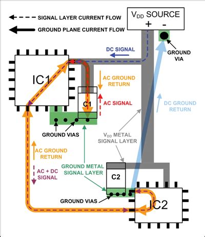
Implementing Star Grounding for Analog and Digital Ground Separation
To effectively implement star grounding for analog and digital ground separation, follow these steps:
-
Identify the central ground point: Choose a location for the central ground point, typically near the power supply or the point where the analog and digital grounds meet.
-
Connect analog grounds: Route all analog ground connections to the central ground point, keeping the traces as short and direct as possible.
-
Connect digital grounds: Similarly, route all digital ground connections to the central ground point, keeping the traces separate from the analog ground traces.
-
Use ground planes: Whenever possible, use ground planes instead of individual traces to provide a low-impedance path for return currents and minimize ground noise.
-
Avoid ground loops: Ensure that there are no multiple paths for ground currents to flow, as this can create ground loops and introduce noise.
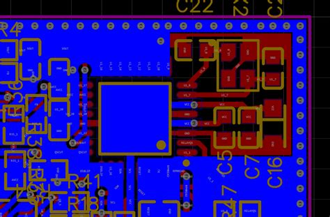
Example Star Grounding Layout
| Component | Ground Connection |
|---|---|
| Analog IC1 | Analog Ground Plane |
| Analog IC2 | Analog Ground Plane |
| Digital IC1 | Digital Ground Plane |
| Digital IC2 | Digital Ground Plane |
| Power Supply | Central Ground Point |

Challenges and Considerations
While star grounding is an effective technique for analog and digital ground separation, there are some challenges and considerations to keep in mind:
-
PCB layout complexity: Implementing star grounding can make PCB layouts more complex, especially in dense designs with limited space.
-
Increased trace lengths: Routing all ground connections to a central point may result in longer trace lengths, which can impact signal integrity and EMC performance.
-
Current capacity: The central ground point must be capable of handling the total current from all connected circuits without introducing voltage drops or thermal issues.
-
Frequency-dependent effects: At high frequencies, the effectiveness of star grounding may be reduced due to parasitic inductances and capacitances in the ground paths.
Alternatives to Star Grounding
In some cases, star grounding may not be the most suitable option for analog and digital ground separation. Alternative techniques include:
-
Partitioned ground planes: Splitting the ground plane into separate analog and digital sections, with a single connection point between them.
-
Hybrid grounding: Combining star grounding with other techniques, such as partitioned ground planes or multi-point grounding, to optimize performance for specific design requirements.
-
Isolated grounding: Using galvanic isolation techniques, such as opto-isolators or transformers, to completely isolate analog and digital grounds.
Frequently Asked Questions (FAQ)
-
Q: Is star grounding always the best choice for analog and digital ground separation?
A: While star grounding is a proven technique for minimizing ground noise and improving signal integrity, it may not always be the most suitable choice. Factors such as PCB layout complexity, trace lengths, and frequency-dependent effects should be considered when deciding on the best grounding strategy for a specific design. -
Q: Can I use a single ground plane for both analog and digital circuits?
A: It is generally not recommended to use a single ground plane for both analog and digital circuits, as this can lead to noise coupling and signal integrity issues. Separating the analog and digital grounds, either through star grounding or other techniques, helps to minimize these problems. -
Q: How do I choose the central ground point for star grounding?
A: The central ground point should be chosen based on several factors, including the location of the power supply, the point where analog and digital grounds meet, and the overall system layout. Ideally, the central ground point should be located in a way that minimizes trace lengths and provides a low-impedance path for return currents. -
Q: What are the consequences of not separating analog and digital grounds?
A: Failing to separate analog and digital grounds can lead to several issues, including increased ground noise, reduced signal integrity, and potential EMC compliance problems. This can result in poor system performance, inaccurate measurements, and even device malfunction. -
Q: Can star grounding be used in conjunction with other grounding techniques?
A: Yes, star grounding can be used in combination with other techniques, such as partitioned ground planes or multi-point grounding, to optimize performance for specific design requirements. This hybrid approach allows designers to take advantage of the benefits of star grounding while addressing any limitations or challenges that may arise in a particular application.
Conclusion
Star grounding is a powerful technique for separating analog and digital grounds in mixed-signal systems, helping to minimize ground noise, improve signal integrity, and ensure proper system performance. By carefully implementing star grounding and considering factors such as PCB layout, trace lengths, and current capacity, designers can effectively mitigate the challenges associated with analog and digital ground separation.
However, it is essential to recognize that star grounding may not always be the most suitable choice for every design. Alternative techniques, such as partitioned ground planes, hybrid grounding, and isolated grounding, should also be considered based on the specific requirements and constraints of the application.
Ultimately, the key to successful analog and digital ground separation lies in understanding the unique needs of the system, carefully evaluating the available grounding options, and selecting the approach that best balances performance, reliability, and design complexity.
Leave a Reply