Introduction to PCB Routing Angles
Printed Circuit Board (PCB) routing is a crucial aspect of electronic design, as it determines the efficiency and reliability of the final product. One of the most debated topics in PCB routing is the choice between 45-degree and 90-degree angles. This article will explore the myths surrounding PCB routing angles and provide a comprehensive comparison between 45-degree and 90-degree angles.
The Importance of Proper PCB Routing
Proper PCB routing ensures that signals travel efficiently and without interference, minimizing the risk of signal integrity issues and electromagnetic interference (EMI). Optimal routing also helps to reduce the overall size of the PCB, which can lead to cost savings and improved device performance.
Myths About PCB Routing Angles
There are several common myths surrounding PCB routing angles that can lead to suboptimal designs and unnecessary complications. Let’s debunk some of these myths:
Myth 1: 45-Degree Angles Are Always Better Than 90-Degree Angles
One of the most persistent myths in PCB routing is that 45-degree angles are always superior to 90-degree angles. While 45-degree angles can offer some advantages in certain situations, they are not a one-size-fits-all solution.
Advantages of 45-Degree Angles
- Reduced signal reflections
- Improved signal integrity
- Better EMI performance
Disadvantages of 45-Degree Angles
- Increased trace length
- Reduced routing space
- More complex routing algorithms required
Myth 2: 90-Degree Angles Cause Signal Integrity Issues
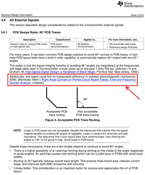
Another common myth is that 90-degree angles inherently cause signal integrity issues. While sharp 90-degree angles can indeed lead to signal reflections and EMI, proper design techniques can mitigate these issues.
Mitigating Signal Integrity Issues with 90-Degree Angles
- Use of curved corners or chamfers
- Proper trace width and spacing
- Adequate ground plane coverage

Comparing 45-Degree and 90-Degree Angles
To make an informed decision between 45-degree and 90-degree angles, it’s essential to understand their respective strengths and weaknesses.
Signal Integrity
| Angle | Advantages | Disadvantages |
|---|---|---|
| 45-Degree | Reduced signal reflections | Increased trace length |
| 90-Degree | Shorter trace length | Potential for signal reflections |
Routing Efficiency
| Angle | Advantages | Disadvantages |
|---|---|---|
| 45-Degree | Better utilization of diagonal routing | More complex routing algorithms required |
| 90-Degree | Simpler routing algorithms | Less efficient use of routing space |
EMI Performance
| Angle | Advantages | Disadvantages |
|---|---|---|
| 45-Degree | Reduced EMI due to smoother transitions | Increased trace length may increase EMI |
| 90-Degree | Shorter trace length may reduce EMI | Sharp corners can increase EMI |

Best Practices for PCB Routing Angles
To achieve optimal PCB routing, consider the following best practices:
- Use a combination of 45-degree and 90-degree angles based on the specific requirements of your design.
- Avoid sharp 90-degree angles whenever possible, opting for curved corners or chamfers instead.
- Maintain proper trace width and spacing to minimize signal integrity issues and EMI.
- Ensure adequate ground plane coverage to provide a low-impedance return path for signals.
- Use simulation tools to analyze and optimize your routing design before fabrication.

Frequently Asked Questions (FAQ)
1. When should I use 45-degree angles in PCB routing?
45-degree angles are particularly useful in high-speed designs where signal integrity is a primary concern. They can help reduce signal reflections and improve EMI performance by providing smoother transitions between traces.
2. Can I use 90-degree angles in my PCB design without causing issues?
Yes, you can use 90-degree angles in your PCB design as long as you follow best practices such as using curved corners or chamfers, maintaining proper trace width and spacing, and ensuring adequate ground plane coverage.
3. Is it always necessary to use a combination of 45-degree and 90-degree angles?
No, it’s not always necessary to use both 45-degree and 90-degree angles in your PCB design. The choice between the two depends on the specific requirements of your project, such as signal integrity, routing efficiency, and EMI performance.
4. How can I minimize signal integrity issues when using 90-degree angles?
To minimize signal integrity issues when using 90-degree angles, consider using curved corners or chamfers instead of sharp angles, maintain proper trace width and spacing, and ensure adequate ground plane coverage.
5. What tools can I use to optimize my PCB routing design?
There are several PCB design and simulation tools available that can help you optimize your routing design, such as Altium Designer, Cadence OrCAD, and Mentor Graphics PADS. These tools often include features for analyzing signal integrity, EMI performance, and routing efficiency.
Conclusion
The choice between 45-degree and 90-degree angles in PCB routing is not a simple one, as both have their advantages and disadvantages. By understanding the myths surrounding PCB routing angles and following best practices, you can create efficient and reliable PCB designs that meet your specific requirements. Remember to consider factors such as signal integrity, routing efficiency, and EMI performance when making your decision, and don’t hesitate to use a combination of both angles when appropriate.

Leave a Reply