Introduction to Magnetism and Sensors
Magnetism is a fundamental force of nature that has fascinated humans for centuries. From the ancient Greeks’ discovery of lodestones to the modern-day applications in electronics and engineering, the study of magnetism has led to numerous technological advancements. One such advancement is the development of magnetic sensors, which detect and measure magnetic fields. Among these sensors, the Hall effect sensor has gained significant popularity due to its versatility and reliability in various applications, particularly in printed circuit boards (PCBs).
In this article, we will delve into the world of magnetism, exploring the principles behind Hall effect sensors and their applications in PCBs. We will discuss the advantages and limitations of these sensors, as well as provide insights into their selection and implementation in different scenarios.
Understanding Magnetic Fields and the Hall Effect
Magnetic Fields
A magnetic field is a region around a magnetic material or a moving electric charge within which the force of magnetism acts. Magnetic fields are represented by lines of force, which indicate the direction and strength of the field at any given point. The SI unit for magnetic field strength is the Tesla (T), named after the renowned scientist Nikola Tesla.
Magnetic fields can be classified into two types:
1. Permanent Magnetic Fields: These fields are produced by permanent magnets, which are materials that have been magnetized and retain their magnetic properties indefinitely. Examples include ferromagnetic materials like iron, nickel, and cobalt.
- Induced Magnetic Fields: These fields are generated by the flow of electric current through a conductor. The strength of the induced magnetic field is proportional to the current flowing through the conductor.
The Hall Effect
The Hall effect, discovered by Edwin Hall in 1879, is a phenomenon that occurs when a magnetic field is applied perpendicular to a current-carrying conductor. The interaction between the magnetic field and the moving charges in the conductor results in a transverse voltage, known as the Hall voltage, which is proportional to the strength of the magnetic field.
The Hall effect can be mathematically represented by the following equation:
V_H = (I × B) / (n × q × t)
Where:
– V_H is the Hall voltage
– I is the current flowing through the conductor
– B is the magnetic field strength
– n is the charge carrier density
– q is the charge of the carrier (electron or hole)
– t is the thickness of the conductor
The Hall effect has found numerous applications in the field of magnetic sensing, as it allows for the detection and measurement of magnetic fields using a simple and compact device called the Hall effect sensor.
Hall Effect Sensors
Working Principle
A Hall effect sensor is a transducer that converts a magnetic field into an electrical signal. It consists of a thin sheet of semiconductor material, usually silicon or gallium arsenide, with a constant current flowing through it. When a magnetic field is applied perpendicular to the current flow, a Hall voltage is generated across the width of the sensor, which is proportional to the strength of the magnetic field.
The basic structure of a Hall effect sensor is shown in the figure below:
The Hall voltage generated by the sensor can be amplified and processed using electronic circuits to obtain a usable output signal. This output signal can be in the form of an analog voltage or a digital signal, depending on the specific application and the type of sensor used.
Types of Hall Effect Sensors
Hall effect sensors can be classified into three main types based on their output characteristics:
-
Analog Hall Effect Sensors: These sensors provide a continuous analog output voltage that varies linearly with the applied magnetic field. They are suitable for applications that require precise measurements of magnetic field strength, such as in position sensing and current sensing.
-
Digital Hall Effect Sensors: These sensors have a built-in comparator that converts the analog Hall voltage into a digital output signal. The output switches between two discrete levels (ON/OFF) when the magnetic field strength exceeds a certain threshold. Digital Hall effect sensors are commonly used in applications that require simple switching functions, such as in proximity sensing and rotary encoding.
-
Bipolar Hall Effect Sensors: These sensors are capable of detecting both the magnitude and polarity of a magnetic field. They provide an output voltage that varies proportionally with the strength and direction of the applied magnetic field. Bipolar Hall effect sensors are useful in applications that require the detection of both north and south poles of a magnet, such as in motor commutation and magnetic field mapping.
Advantages of Hall Effect Sensors
Hall effect sensors offer several advantages that make them popular choices for magnetic sensing applications:
-
Non-contact sensing: Hall effect sensors can detect magnetic fields without physical contact with the target object, making them suitable for applications where contactless sensing is required, such as in rotary encoders and gear tooth sensors.
-
High reliability: Due to their solid-state construction and lack of moving parts, Hall effect sensors are highly reliable and have a long lifespan. They are resistant to shock, vibration, and dust, making them suitable for use in harsh environments.
-
Wide operating temperature range: Hall effect sensors can operate over a wide temperature range, typically from -40°C to +125°C, making them suitable for use in various industrial and automotive applications.
-
Small size and low power consumption: Hall effect sensors are available in compact packages and consume very little power, making them ideal for integration into space-constrained devices and battery-powered applications.
-
Versatility: Hall effect sensors can be used to detect a wide range of magnetic field strengths, from weak fields generated by small permanent magnets to strong fields produced by electromagnets. They can also be used to measure both static and dynamic magnetic fields.
Limitations of Hall Effect Sensors
Despite their numerous advantages, Hall effect sensors also have some limitations that should be considered when selecting them for a particular application:
-
Sensitivity to temperature: The output of Hall effect sensors can be affected by changes in temperature, which can lead to measurement errors if not compensated for. Temperature compensation techniques, such as using a temperature sensor in conjunction with the Hall effect sensor, can help mitigate this issue.
-
Limited spatial resolution: The size of the Hall effect sensor determines its spatial resolution, which is the minimum distance between two adjacent magnetic field sources that can be distinguished by the sensor. Smaller sensors offer higher spatial resolution but may have lower sensitivity and signal-to-noise ratio.
-
Susceptibility to external magnetic fields: Hall effect sensors can be influenced by external magnetic fields, such as those generated by nearby electrical devices or the Earth’s magnetic field. Proper shielding and calibration techniques can help minimize the impact of external magnetic fields on the sensor’s performance.
-
Limited bandwidth: The bandwidth of Hall effect sensors is typically limited by the response time of the semiconductor material and the associated electronic circuits. High-frequency magnetic fields may not be accurately detected by Hall effect sensors with limited bandwidth.

Applications of Hall Effect Sensors in PCBs
Hall effect sensors have found numerous applications in various industries, ranging from automotive and consumer electronics to industrial automation and robotics. In the context of printed circuit boards (PCBs), Hall effect sensors are commonly used for the following purposes:
Current Sensing
Hall effect sensors can be used to measure the current flowing through a conductor on a PCB by detecting the magnetic field generated by the current. This technique, known as Hall effect current sensing, offers several advantages over traditional methods like shunt resistors:
-
Galvanic isolation: Hall effect sensors provide galvanic isolation between the current-carrying conductor and the sensing circuit, eliminating the need for opto-isolators or isolation amplifiers.
-
Non-intrusive measurement: Hall effect sensors do not require any electrical connection to the conductor being measured, making them suitable for non-intrusive current monitoring in power electronics and motor control applications.
-
Wide dynamic range: Hall effect sensors can measure currents ranging from a few milliamps to several hundred amps, depending on the sensor’s sensitivity and the magnetic core used to concentrate the magnetic field.
To implement Hall effect current sensing on a PCB, the current-carrying conductor is routed through a magnetic core, such as a ferrite toroid, which concentrates the magnetic field generated by the current. The Hall effect sensor is placed in the air gap of the magnetic core, where it detects the magnetic field and generates an output voltage proportional to the current.
Position Sensing
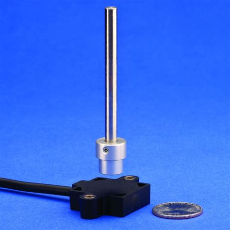
Hall effect sensors can be used to detect the position of a moving object on a PCB, such as a linear actuator or a rotary encoder. By placing a permanent magnet on the moving object and a Hall effect sensor on the PCB, the position of the object can be determined based on the strength and polarity of the magnetic field detected by the sensor.
For linear position sensing, a bipolar Hall effect sensor is typically used in conjunction with a multipole magnetic strip attached to the moving object. As the object moves along the PCB, the sensor detects the alternating north and south poles of the magnetic strip and generates a sinusoidal output signal. The position of the object can be determined by counting the number of magnetic pole pairs detected by the sensor.
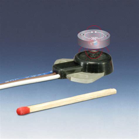
For rotary position sensing, a Hall effect sensor is placed near a rotating disc or shaft that has a permanent magnet attached to it. As the disc or shaft rotates, the sensor detects the changing magnetic field and generates a series of pulses that can be used to determine the angular position and speed of the rotating object.
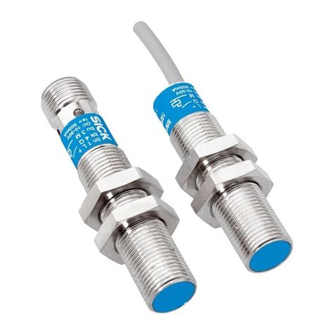
Proximity Sensing
Hall effect sensors can be used to detect the presence or absence of a magnetic object in close proximity to the sensor. This principle is commonly used in proximity switches, where a permanent magnet is attached to a moving object, such as a door or a valve, and a Hall effect sensor is placed on the PCB near the magnet.
When the moving object is close to the sensor, the magnetic field strength detected by the sensor exceeds a predetermined threshold, causing the sensor’s output to switch from one state to another (e.g., from LOW to HIGH). This digital output signal can be used to trigger an action, such as turning on an LED or activating a relay.
Proximity sensing using Hall effect sensors is widely used in various applications, such as:
-
Door and window sensors: Hall effect sensors can detect the opening and closing of doors and windows in security systems and home automation applications.
-
Liquid level detection: By placing a floating magnet on the surface of a liquid and a Hall effect sensor on the PCB below the container, the liquid level can be detected based on the proximity of the magnet to the sensor.
-
Gear tooth sensing: Hall effect sensors can detect the presence or absence of ferromagnetic gear teeth in automotive and industrial applications, such as in crankshaft position sensing and wheel speed sensing.
Selecting and Implementing Hall Effect Sensors in PCBs
When selecting and implementing Hall effect sensors in PCBs, several factors should be considered to ensure optimal performance and reliability:
Sensor Sensitivity and Range
The sensitivity and range of the Hall effect sensor should be chosen based on the specific application requirements. Factors to consider include the strength of the magnetic field to be detected, the distance between the sensor and the magnetic source, and the desired resolution and accuracy of the measurement.
For applications that require high sensitivity, such as in current sensing or position sensing, a sensor with a high magnetic field sensitivity (measured in mV/mT or mV/G) should be selected. For applications that involve detecting strong magnetic fields or large distances between the sensor and the magnet, a sensor with a wide magnetic field range (measured in mT or G) should be chosen.
Sensor Output Type
The output type of the Hall effect sensor should be selected based on the requirements of the application and the interface with other components on the PCB. Analog output sensors provide a continuous voltage output that varies linearly with the magnetic field strength, while digital output sensors provide a switched output that changes state at a predetermined magnetic field threshold.
Analog output sensors are suitable for applications that require precise measurement of magnetic field strength, such as in position sensing and current sensing. Digital output sensors are suitable for applications that require simple switching functions, such as in proximity sensing and gear tooth sensing.
PCB Layout Considerations
Proper PCB layout is crucial for the optimal performance of Hall effect sensors. The following guidelines should be followed when designing the PCB layout:
-
Placement: The Hall effect sensor should be placed as close as possible to the magnetic source to maximize the detected magnetic field strength. The sensor should also be oriented such that the sensitive axis of the sensor is aligned with the direction of the magnetic field.
-
Shielding: The sensor and its associated circuitry should be shielded from external magnetic fields and electromagnetic interference (EMI) using techniques such as ground planes, ferrite beads, and shielded cables.
-
Routing: The traces connecting the sensor to other components on the PCB should be kept as short as possible to minimize the effect of parasitic inductance and capacitance. The traces should also be routed away from high-current or high-frequency signals to avoid coupling of noise into the sensor output.
-
Decoupling: Adequate decoupling capacitors should be placed close to the sensor’s power supply pins to minimize the effect of supply voltage fluctuations on the sensor output.
Signal Conditioning and Processing
The output signal from the Hall effect sensor may require further conditioning and processing to obtain a usable measurement or control signal. Analog signal conditioning techniques, such as amplification, filtering, and offset correction, can be used to improve the signal-to-noise ratio and remove any unwanted frequency components from the sensor output.
For digital output sensors, the signal processing may involve debouncing the switched output to eliminate any false triggers due to noise or vibration. This can be achieved using hardware debounce circuits or software debounce algorithms implemented in a microcontroller or FPGA.
Conclusion
Hall effect sensors have revolutionized the field of magnetic sensing, offering a reliable and versatile solution for a wide range of applications in PCBs. By understanding the principles behind these sensors and their application-specific requirements, engineers and designers can select and implement the most suitable Hall effect sensors for their projects.
As technology continues to advance, we can expect to see further improvements in the performance and functionality of Hall effect sensors, leading to even more innovative applications in the future. With their non-contact sensing capabilities, high reliability, and small size, Hall effect sensors will undoubtedly continue to play a crucial role in the development of modern electronic devices and systems.
Frequently Asked Questions (FAQ)
1. What is the difference between analog and digital Hall effect sensors?
Analog Hall effect sensors provide a continuous output voltage that varies linearly with the magnetic field strength, while digital Hall effect sensors have a built-in comparator that converts the analog output into a switched digital signal when the magnetic field strength exceeds a certain threshold.
2. Can Hall effect sensors be used to measure AC magnetic fields?
Yes, Hall effect sensors can be used to measure both DC and AC magnetic fields. However, for AC magnetic field measurement, the bandwidth of the sensor and the associated signal conditioning circuitry should be sufficient to capture the frequency components of the AC field.
3. How does temperature affect the performance of Hall effect sensors?
The output of Hall effect sensors can be affected by changes in temperature, leading to measurement errors if not compensated for. Temperature compensation techniques, such as using a temperature sensor in conjunction with the Hall effect sensor and applying correction factors based on the temperature reading, can help mitigate this issue.
4. What is the typical power consumption of Hall effect sensors?
Hall effect sensors generally have low power consumption, typically in the range of a few milliwatts to tens of milliwatts, depending on the specific sensor and its operating conditions. Low-power Hall effect sensors are available for battery-powered and energy-constrained applications.
5. How can external magnetic fields be minimized when using Hall effect sensors?
To minimize the impact of external magnetic fields on Hall effect sensors, various techniques can be employed, such as:
1. Using magnetic shielding materials, such as mu-metal or ferrite, to enclose the sensor and its associated circuitry.
2. Orienting the sensor such that its sensitive axis is perpendicular to the direction of the external magnetic field.
3. Implementing differential sensing techniques, where two Hall effect sensors are used in a differential configuration to cancel out the common-mode external magnetic field.
4. Applying digital signal processing techniques, such as averaging and filtering, to remove the effect of external magnetic field noise from the sensor output.
Leave a Reply