Introduction to PCB Testing
Printed circuit board (PCB) testing is a crucial step in the electronics manufacturing process to ensure the quality, reliability, and functionality of the final product. Whether you are a hobbyist or a professional, having the right PCB testing equipment is essential for identifying and resolving issues before the boards are assembled into the final product.
In this article, we will discuss the essential equipment for beginners to get started with PCB testing, including multimeters, oscilloscopes, power supplies, and more. We will also provide guidance on how to choose the right equipment based on your specific needs and budget.
Types of PCB Testing
Before diving into the essential equipment, let’s briefly discuss the different types of PCB testing:
-
Visual Inspection: This is the first step in PCB testing, where the board is visually checked for any obvious defects, such as incorrect component placement, solder bridges, or damaged traces.
-
Continuity Testing: This test verifies that the electrical connections between components are intact and that there are no short circuits or open circuits.
-
Voltage Testing: This test measures the voltage levels at various points on the PCB to ensure that they are within the expected range.
-
Functional Testing: This test verifies that the PCB functions as intended by applying input signals and measuring the output signals.
-
In-Circuit Testing (ICT): This test involves using specialized equipment to test individual components on the PCB while they are still connected to the board.
-
Boundary Scan Testing: This test uses built-in test circuitry to test the interconnections between components on the PCB.
Essential PCB Testing Equipment
1. Multimeter
A multimeter is an essential tool for measuring voltage, current, and resistance on a PCB. It is a versatile instrument that can be used for continuity testing, voltage testing, and component testing.
When choosing a multimeter for PCB testing, consider the following features:
- Accuracy: Look for a multimeter with high accuracy, typically within 0.5% for voltage and resistance measurements.
- Resolution: Choose a multimeter with a resolution of at least 4.5 digits for more precise measurements.
- Auto-ranging: This feature automatically selects the appropriate range for the measurement, making it easier to use.
- Continuity Testing: Make sure the multimeter has a continuity testing function with an audible beep for quick testing.
- Protection: Look for a multimeter with overload protection to prevent damage from accidental high voltage or current inputs.
Here are some recommended multimeters for PCB testing:
| Brand | Model | Price Range | Key Features |
|---|---|---|---|
| Fluke | 87V | $400 – $500 | High accuracy, rugged design, auto-ranging |
| Amprobe | AM-510 | $50 – $100 | Affordable, auto-ranging, continuity testing |
| Extech | EX330 | $50 – $100 | Compact, auto-ranging, non-contact voltage detection |
| Klein Tools | MM600 | $50 – $100 | Auto-ranging, continuity testing, easy to use |
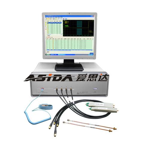
2. Oscilloscope
An oscilloscope is used to visualize and measure time-varying signals on a PCB. It displays the waveform of the signal, allowing you to measure parameters such as voltage, frequency, and rise/fall times.
When choosing an oscilloscope for PCB testing, consider the following features:
- Bandwidth: Choose an oscilloscope with a bandwidth that is at least five times the highest frequency of the signals you intend to measure.
- Sample Rate: A higher sample rate allows for more accurate representation of the signal. Look for an oscilloscope with a sample rate of at least 2.5 times the bandwidth.
- Number of Channels: Determine how many signals you need to measure simultaneously and choose an oscilloscope with the appropriate number of channels.
- Resolution: Higher resolution allows for more precise measurements. Look for an oscilloscope with at least 8-bit resolution.
- Triggering: Make sure the oscilloscope has advanced triggering options, such as edge, pulse, and logic triggering, to capture specific events.
Here are some recommended oscilloscopes for PCB testing:
| Brand | Model | Price Range | Key Features |
|---|---|---|---|
| Tektronix | TBS1052B | $400 – $600 | 50 MHz bandwidth, 2 channels, 7-inch display |
| Rigol | DS1052E | $300 – $500 | 50 MHz bandwidth, 2 channels, 5.6-inch display |
| Siglent | SDS1102CML | $300 – $500 | 100 MHz bandwidth, 2 channels, 7-inch display |
| Hantek | DSO5102P | $200 – $400 | 100 MHz bandwidth, 2 channels, 7-inch display |
3. Power Supply
A power supply is used to provide stable and adjustable DC voltage to the PCB during testing. It is essential for powering the board and testing its functionality under different voltage conditions.
When choosing a power supply for PCB testing, consider the following features:
- Voltage Range: Choose a power supply with a voltage range that covers the voltage requirements of the PCB you are testing.
- Current Capacity: Make sure the power supply can provide enough current to power the PCB and any connected test equipment.
- Regulation: Look for a power supply with good line and load regulation to ensure stable voltage output.
- Protection: Choose a power supply with overload, short circuit, and over-temperature protection to prevent damage to the PCB and the power supply itself.
- Programmability: Consider a programmable power supply if you need to automate the testing process or test the PCB under different voltage conditions.
Here are some recommended power supplies for PCB testing:
| Brand | Model | Price Range | Key Features |
|---|---|---|---|
| Keithley | 2231A-30-3 | $800 – $1000 | Triple output, 30V/3A per output, programmable |
| Siglent | SPD3303X-E | $400 – $600 | Triple output, 30V/3A per output, programmable |
| Rigol | DP832 | $800 – $1000 | Triple output, 30V/3A per output, programmable |
| B&K Precision | 9130B | $300 – $500 | Single output, 30V/3A, programmable |
4. Logic Analyzer
A logic analyzer is used to capture and display digital signals on a PCB. It is especially useful for debugging digital circuits and analyzing the timing relationships between signals.
When choosing a logic analyzer for PCB testing, consider the following features:
- Number of Channels: Choose a logic analyzer with enough channels to capture all the digital signals you need to analyze simultaneously.
- Sample Rate: Higher sample rates allow for more precise timing measurements. Look for a logic analyzer with a sample rate of at least 500 MS/s.
- Memory Depth: Deeper memory allows for longer capture times. Choose a logic analyzer with a memory depth that suits your needs.
- Triggering: Look for a logic analyzer with advanced triggering options, such as pattern, edge, and state triggering, to capture specific events.
- Protocol Decoding: If you are working with standard communication protocols, such as I2C, SPI, or UART, consider a logic analyzer with built-in protocol decoding.
Here are some recommended logic analyzers for PCB testing:
| Brand | Model | Price Range | Key Features |
|---|---|---|---|
| Saleae | Logic Pro 16 | $600 – $800 | 16 channels, 500 MS/s, protocol decoding |
| Digilent | Digital Discovery | $200 – $400 | 24 channels, 800 MS/s, protocol decoding |
| Keysight | 16850 Series | $1000 – $1500 | 68 channels, 2.5 GS/s, protocol decoding |
5. Soldering and Desoldering Equipment
Soldering and desoldering equipment is essential for making and modifying connections on a PCB during testing and debugging.
When choosing soldering and desoldering equipment, consider the following:
- Soldering Iron: Look for a soldering iron with adjustable temperature control and a variety of tip sizes for different applications.
- Desoldering Pump: A desoldering pump, also known as a solder sucker, is used to remove solder from joints quickly.
- Desoldering Wick: Desoldering wick, also known as desoldering braid, is used to absorb molten solder from joints.
- Fume Extractor: A fume extractor helps remove harmful fumes generated during soldering.
Here are some recommended soldering and desoldering equipment:
| Brand | Model | Price Range | Key Features |
|---|---|---|---|
| Hakko | FX888D | $80 – $120 | Digital temperature control, quick heating |
| Weller | WE1010 | $200 – $300 | Digital temperature control, multiple tip options |
| X-Tronic | Model 3020-XTS | $50 – $100 | Affordable, adjustable temperature, stand included |

Setting Up a PCB Testing Workspace
Now that you have the essential equipment for PCB testing, it’s important to set up a proper workspace. Here are some tips:
-
Choose a Dedicated Space: Set aside a dedicated area for PCB testing, away from distractions and with good lighting.
-
Use an ESD Mat: An electrostatic discharge (ESD) mat helps protect your PCBs and equipment from damage caused by static electricity.
-
Organize Your Tools: Keep your tools organized and easily accessible. Use tool boxes, bins, or pegboards to keep your workspace tidy.
-
Ensure Proper Ventilation: Make sure your workspace has proper ventilation, especially when soldering, to avoid inhaling harmful fumes.
-
Maintain Good Posture: Use a comfortable chair and adjust your workspace height to maintain good posture and avoid strain during long testing sessions.
PCB Testing Techniques
Visual Inspection
Visual inspection is the first step in PCB testing. Here’s how to perform a thorough visual inspection:
-
Check for Obvious Defects: Look for any obvious defects, such as incorrect component placement, solder bridges, or damaged traces.
-
Use a Magnifying Glass: Use a magnifying glass to inspect smaller components and solder joints for any issues.
-
Check Component Orientation: Verify that all components are placed in the correct orientation, especially polarized components like capacitors and diodes.
-
Inspect Solder Joints: Check solder joints for any signs of poor quality, such as cold joints, insufficient solder, or excessive solder.
Continuity Testing
Continuity testing is used to verify that the electrical connections between components are intact and that there are no short circuits or open circuits. Here’s how to perform continuity testing:
-
Set Your Multimeter: Set your multimeter to the continuity testing mode, which is usually indicated by a beep symbol.
-
Test Continuity: Touch the probes to the points you want to test. If there is continuity, the multimeter will beep.
-
Check for Short Circuits: Test for short circuits between adjacent traces or pins by touching one probe to each point. If there is a short circuit, the multimeter will beep.
-
Check for Open Circuits: Test for open circuits by touching the probes to the points that should be connected. If there is an open circuit, the multimeter will not beep.
Voltage Testing
Voltage testing is used to measure the voltage levels at various points on the PCB to ensure that they are within the expected range. Here’s how to perform voltage testing:
-
Set Your Multimeter: Set your multimeter to the voltage testing mode, and select the appropriate voltage range (DC or AC).
-
Power the PCB: Power the PCB using a power supply, ensuring that the voltage and current levels are within the PCB’s specifications.
-
Measure Voltage Levels: Touch the probes to the points you want to measure, making sure to connect the black probe to ground and the red probe to the point of interest.
-
Compare with Expected Values: Compare the measured voltage levels with the expected values based on the PCB’s schematic or design specifications.
Functional Testing
Functional testing is used to verify that the PCB functions as intended by applying input signals and measuring the output signals. Here’s how to perform functional testing:
-
Set Up Test Equipment: Connect the necessary test equipment, such as oscilloscopes, function generators, or logic analyzers, to the PCB.
-
Apply Input Signals: Apply the appropriate input signals to the PCB, following the test plan or design specifications.
-
Measure Output Signals: Measure the output signals using the test equipment, and compare them with the expected values.
-
Verify Functionality: Verify that the PCB functions as intended under various input conditions and scenarios.
FAQ
1. What is the most important piece of equipment for PCB testing?
The most important piece of equipment for PCB testing is a multimeter. It is a versatile tool that can be used for continuity testing, voltage testing, and component testing, making it essential for debugging and verifying PCB functionality.
2. Do I need an oscilloscope for PCB testing?
An oscilloscope is not strictly necessary for basic PCB testing, but it is a valuable tool for more advanced testing and debugging. If you are working with high-frequency signals or need to analyze time-varying waveforms, an oscilloscope is essential.
3. Can I use a generic power supply for PCB testing?
While a generic power supply can be used for basic PCB testing, it is recommended to use a dedicated power supply designed for electronics testing. These power supplies offer better voltage regulation, current limiting, and protection features, which can help prevent damage to your PCB and test equipment.
4. How do I choose the right soldering iron for PCB testing?
When choosing a soldering iron for PCB testing, look for one with adjustable temperature control, a variety of tip sizes, and good build quality. Some popular brands include Hakko, Weller, and X-Tronic. Consider your budget and the types of projects you will be working on when making your selection.
5. What safety precautions should I take when testing PCBs?
When testing PCBs, always follow these safety precautions:
- Wear safety glasses to protect your eyes from debris or splashes.
- Use an ESD mat and wear an ESD wrist strap to prevent damage from electrostatic discharge.
- Ensure proper ventilation when soldering to avoid inhaling harmful fumes.
- Disconnect power sources before making any connections or modifications to the PCB.
- Be aware of the voltage and current levels you are working with, and take appropriate precautions to avoid electrical shock.
Conclusion
PCB testing is a critical skill for anyone working with electronics, whether as a hobby or professionally. By investing in the right equipment and setting up a proper workspace, you can efficiently debug and verify your PCB designs, ensuring their quality and functionality.
Remember to start with the essential equipment, such as a multimeter and power supply, and expand your toolkit as your needs and skills grow. Always prioritize safety and follow best practices when testing your PCBs.
With practice and patience, you will develop the skills and knowledge needed to become proficient in PCB testing, enabling you to create reliable and high-quality electronic products.
Leave a Reply