What are PCB Reference Designators?
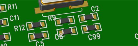
PCB reference designators are the unique alphanumeric identifiers assigned to each component on a printed circuit board (PCB). They serve as a way to uniquely identify and locate specific components on the board during design, assembly, testing, and troubleshooting.
Reference designators typically consist of one or two letters followed by a number. The letter prefixes are standardized and indicate the type of component:
| Prefix | Component Type |
|---|---|
| C | Capacitors |
| D | Diodes |
| J | Connectors |
| L | Inductors |
| Q | Transistors |
| R | Resistors |
| U | Integrated Circuits |
| Y | Crystals/Oscillators |
For example, C23 would refer to the 23rd capacitor on the board, while U7 would be the 7th integrated circuit.
Why are Reference Designators Important?
Consistently using reference designators is critical for several reasons:
-
Communication – Ref des provide a common language for designers, manufacturers, and technicians to refer to specific components. This is essential for conveying design intent, assembly instructions, and troubleshooting guidance.
-
Design Review – During schematic and layout reviews, ref des allow reviewers to easily cross-reference between the schematic, BOM, and layout to verify the design.
-
Assembly – Pick and place files and assembly drawings rely on ref des to specify where each component should be placed on the PCB.
-
Testing and Troubleshooting – When a faulty board needs to be debugged, ref des enable technicians to quickly locate and check suspicious components called out by test procedures or inspection.
-
Future Revisions – If updates or repairs need to be made to the board later, ref des ensure the correct components are changed.
So while it may seem tedious to assign and track hundreds of ref des during design, they are vital for producing a manufacturable, testable PCB. Fortunately, Altium Designer offers tools to make managing reference designators much easier.
Defining Component Reference Designators in Altium
When you add a component to an Altium schematic, a reference designator is automatically assigned according to customizable formatting rules. To view or change these settings:
- Go to Tools -> Preferences -> Schematic -> Defaults
- In the Default Reference Designators section, you can specify the prefix and numerical order for each component type
For example, you may want resistors to be labeled R1, R2, R3, etc., capacitors as C1, C2, C3, and so on. Altium will automatically increment the number for each instance of that component type placed.
You can also manually override the default ref des for a component directly in the schematic:
- Double-click the component to open the Component Properties window
- Edit the Designator field to the desired name
- Click OK to apply the change
Altium will alert you if you enter a duplicate designator that is already used elsewhere in the schematic.
Naming Power Symbols
One common gotcha is that power symbols (e.g. VCC, GND) are treated differently than other schematic symbols. By default they are designated with the # prefix. You can change this in the Preferences by:
- Go to Tools -> Preferences -> Schematic -> Power Port
- Set the Default Designator to the desired prefix (e.g. +, -)
Consistently labeling your power nets is important for being able to identify them later when looking at net lists or PCB layouts.
Bulk-Editing Reference Designators
If you need to make wholesale changes to reference designators, going component-by-component is tedious. Luckily Altium offers some bulk editing options.
To change multiple designators at once from the schematic:
- Hold Ctrl and click to select the desired components (or Ctrl+A to select all)
- Press F11 or right-click and choose Find Similar Objects
- In the Replace tab, specify the designator pattern to find and what to replace it with
- Click Replace All to make the substitution
This method is useful if you want to change prefixes or numbering schemes across the entire design. Be careful to preview the changes first to avoid unintended renaming.
You can also edit ref des using a List Panel:
- Go to View -> Panels -> SCH List
- The panel shows a spreadsheet like view of components
- Click a cell in the Designator column to edit it
- Changes will be reflected in the schematic
List panels are helpful for seeing all your components in a tabular view for reviewing and sorting. You can even copy and paste to/from Excel.
Using Reference Designators Across a Project
Reference designators are not just for schematics – they follow the components across all design domains in Altium to keep everything linked together.
Some ways ref des are used:
- PCB Editor – Ref des appear on the silkscreen, in footprint assignments, and in design rule scopes to map components back to the schematic
- BOM – The bill of materials is generated from the schematic ref des to create a master list for purchasing and assembly
- PCBA Views – PCB views annotate the layout with ref des to help coordinate manufacturing, assembly and testing
- ActiveBOM – HTML BOMs use ref des to generate interactive component lists linked to supplier data
- Draftsman – Fabrication and assembly drawings call out components by their ref des
- Cam Editor – Netlists, pick and place, and other manufacturing outputs use ref des to specify component data
Altium manages the synchronization of reference designators across all of these project aspects. If you change a designator in one place, it will automatically ripple that change everywhere so no manual re-entry is needed.
However, there are still some good practices to follow to avoid issues with ref des:
Locking Reference Designators
Once you have the schematic ref des finalized, it’s a good idea to lock them to prevent accidentally changing them later, which could break links to the PCB and CAM data. To do this:
- Select the desired components in the schematic
- Right-click and choose Lock Reference Designators
You can also lock all the designators at once:
1. Go to Tools -> Annotation -> Lock Schematic Designators
To unlock, simply repeat these steps but choose Unlock instead. Locking is a helpful safeguard once the design is ready for layout.
Back-Annotating From the Board
Sometimes you may need to renumber ref des after layout, like if you discover placement works better with a different arrangement. Altium can back-annotate these PCB changes to the schematic to keep them in sync.
- Make the desired designator changes in PCB Editor
- Go to Design -> Import Changes -> From PCB Document in the schematic
- Preview and accept the changes
Back-annotation ensures the schematic matches the final board but be cautious about re-annotating if you’ve already generated manufacturing files, as they would become out of date.
Handling Duplicated Reference Designators
Occasionally you may end up with duplicate ref des, either from copying circuitry, merging projects, or multi-channel designs. Altium will flag these duplicate designators as errors when compiling the project.
To quickly resolve duplicates:
- Go to Reports -> Component -> Component Reference Designators
- Sort by the Quantity column to group duplicates together
- Select the duplicated components and use the F11 bulk rename to uniquify them
Unused ref des (i.e. components not placed on the board) will also show up in this report for easy cleanup.

Referencing Components Across Multiple Sheets
A final challenge with reference designators is dealing with multi-sheet schematics. For small boards a single sheet may suffice, but more complex designs are typically split into functional circuit blocks across multiple sheets.
Altium supports two methods for linking ref des across sheets:
- Ports – Components can be wired to designated port symbols that carry the signal name and ref des to other sheets
- Off-Sheet Connectors – Like ports but with added information about the connection hierarchy
Both methods let you define the logical connections between sheets without needing to redraw the components. The top-level schematic will show the ports/connectors to provide a birds-eye view.
Some benefits of using ports and off-sheet connectors:
- Connections are preserved if blocks are re-arranged
- Fewer wires need to be shown, reducing visual clutter
- Repeated circuitry can be encapsulated and reused
- Flattening the sheets is not necessary for netlisting
- Connections can be made to other projects
When using multi-sheet designs, you will have additional options in the Annotation panel:
* Annotate Across All Sheets – Incrementally number ref des as if all the sheets were flattened
* Annotate Per Sheet – Number each sheet separately, so ref des restart at 1 on each sheet
* Annotate Per Sheet By List – Use a master list of ref des to annotate each sheet
Which mode you choose depends if you want each sheet to have an independent numbering scheme or if you want them treated as a unified whole.
Conclusion
While it may not be the most glamorous part of PCB design, properly defining and tracking component reference designators is essential for project organization, manufacturability, and serviceability.
Altium Designer offers a wide set of tools for efficiently handling ref des across schematics, layouts, and every other aspect of the design process. By understanding the annotation options, cross-sheet referencing methods, and bulk-editing techniques, you can ensure your next PCB has an accurate, synchronized set of reference designators at every stage.
Here are some of the key takeaways:
- Reference designators uniquely identify components and provide a common language for designers, manufacturers, and technicians
- Altium automatically assigns ref des based on customizable rules and includes tools for bulk-editing them across the project
- Locking ref des once the design is finalized prevents accidental changes that could break CAM file linkages
- Multi-sheet schematic designs should use ports or off-sheet connectors to preserve ref des linkages between circuit blocks
- Annotation reports help find and resolve duplicate or missing designators before manufacturing handoff
With smart reference designator management practices and Altium’s robust toolset, you can navigate even the most complex PCB designs with confidence.
Frequently Asked Questions
How do I import reference designators from my CAD library?
Altium supports importing schematic symbols and footprints from external libraries in a variety of formats. To map the reference designators:
- Go to File -> Import -> Library
- Choose the source CAD format
- In the import options, specify the Reference Designator column
- Altium will assign the imported ref des to the components
This allows you to preserve existing ref des from other ECAD tools.
What if I want to use my own custom reference designator scheme?
Altium allows you to define custom ref des prefixes and numbering in the Schematic Preferences -> Defaults section. Simply add a new entry for each desired component type.
For example, you could define:
Motors – MT1, MT2, etc.
* Heaters – HT1, HT2, etc.
Sensors – SEN1, SEN2, etc.
By default these will be numbered incrementally but you can also specify your own per-component numbering manually.
How do I find a component by its reference designator?
There are a few quick ways to find components by ref des:
- Use the Find panel (View -> Panels ->)
a. Select Components from the dropdown
b. Enter the ref des in the Find field - Use the SCH List panel
a. Sort by the Designator column
b. Scan for the desired ref des - Use the SCH Inspector panel
a. Select the component with the desired ref des
b. The Inspector will show detailed properties
You can also search for a component by ref des in the PCB Editor.
Is there a way to export a list of all my reference designators?
Yes, Altium can generate a variety of reports that include reference designators. Some key reports:
- Bill of Materials – Includes ref des and quantity for each unique component
- Component Reference Designators – Shows all ref des used and flags duplicates
- Component List – Tabular listing of every ref des and its properties
- Electrical Net List – Lists nets and the ref des of components they connect
Reports can be exported to Excel, CSV, text, and other formats for external use or scripting.
What happens if I rename a component’s reference designator after generating manufacturing files?
Renaming ref des after generating fabrication/assembly files is risky because it can cause those files to become out of sync with the actual design.
If you must make a ref des change after manufacturing handoff, be sure to:
- Regenerate all CAM and BOM files to pick up the new names
- Inform your manufacturer of the change and provide updated files
- Revise any internal docs, test procedures, etc. that may reference the old des
Whenever possible, it’s best to lock down your ref des before manufacturing to avoid potential errors and confusion from late-stage changes.
Leave a Reply