What are SMD LEDs and Why Use Them in Your PCB Design?
Surface Mount Device Light Emitting Diodes, or SMD LEDs, are small, efficient, and cost-effective components that provide indication and illumination in modern Printed Circuit Board (PCB) designs. SMD LEDs offer several advantages over through-hole LEDs:
- Smaller footprint, allowing for more compact PCB designs
- Automated pick-and-place assembly compatible
- Lower power consumption
- Wide variety of sizes, brightness levels, and color options
- Easy to incorporate into both rigid and flexible PCBs
SMD LEDs are ideal for applications requiring visual feedback, status indication, backlighting, or decorative lighting effects. By carefully selecting the right SMD LEDs and properly integrating them into your PCB layout and Bill of Materials (BOM), you can enhance the functionality and aesthetics of your electronic device.
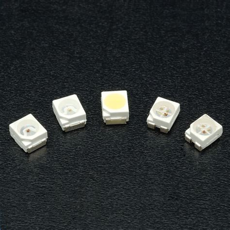
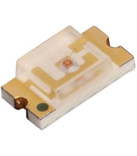
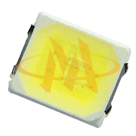
Understanding SMD LED Packages and Sizes
SMD LEDs come in various standard package sizes, each with its own dimensions, power ratings, and optical characteristics. Some common SMD LED packages include:
| Package | Dimensions (mm) | Typical Power |
|---|---|---|
| 0402 | 1.0 x 0.5 | 0.1W |
| 0603 | 1.6 x 0.8 | 0.1W |
| 0805 | 2.0 x 1.25 | 0.2W |
| 1206 | 3.2 x 1.6 | 0.2W |
| 3528 | 3.5 x 2.8 | 1.0W |
| 5050 | 5.0 x 5.0 | 1.0W |
When selecting an SMD LED package for your PCB, consider the following factors:
- Available PCB space and component density
- Required brightness and viewing angle
- Power dissipation and thermal management
- Ease of assembly and rework
- Cost and availability
Smaller packages like 0402 and 0603 are ideal for dense PCB layouts and low-power applications, while larger packages like 3528 and 5050 offer higher brightness and better heat dissipation for power-hungry designs.
Choosing the Right Color and Brightness
SMD LEDs are available in a wide range of colors, from standard red, green, and blue to more exotic options like yellow, orange, purple, and even white. When selecting LED colors for your PCB, consider:
- The purpose of the LED (indication, illumination, decoration)
- The ambient lighting conditions in which the device will be used
- The desired visual impact and aesthetics
- Any industry standards or user expectations for specific colors
In addition to color, the brightness of SMD LEDs is a crucial factor. LED brightness is typically measured in millicandela (mcd) or lumens (lm). The required brightness depends on the application, viewing distance, and ambient light levels. For example:
| Application | Typical Brightness |
|---|---|
| Status Indicator | 50-100 mcd |
| Backlighting | 100-1000 mcd |
| Decorative | 1000+ mcd |
To achieve the desired brightness, you can choose SMD LEDs with the appropriate output, drive them with higher currents, or use multiple LEDs in parallel. However, be mindful of power consumption and heat generation when increasing LED brightness.

Forward Voltage and Current Considerations
Like all diodes, SMD LEDs have a forward voltage (Vf) that must be exceeded for the LED to illuminate. The forward voltage varies depending on the LED color and material:
| Color | Typical Vf |
|---|---|
| Red | 1.8-2.2V |
| Yellow | 2.0-2.4V |
| Green | 2.0-2.6V |
| Blue | 2.6-3.6V |
| White | 2.8-3.8V |
To properly drive an SMD LED, you must provide a current-limiting resistor in series with the LED. The resistor value depends on the supply voltage, LED forward voltage, and desired current. You can calculate the resistor value using the following formula:
R = (Vsupply – Vf) / If
Where:
– R is the resistor value in ohms
– Vsupply is the supply voltage in volts
– Vf is the LED forward voltage in volts
– If is the desired forward current in amps
For example, to drive a red SMD LED with a forward voltage of 2V at 20mA from a 5V supply, the resistor value would be:
R = (5V – 2V) / 0.02A = 150 ohms
When selecting the resistor power rating, ensure it can handle the expected power dissipation:
P = (Vsupply – Vf) * If
In the above example, the resistor power dissipation would be:
P = (5V – 2V) * 0.02A = 0.06W
A standard 1/8W or 1/4W resistor would be sufficient for this application.
PCB Layout Considerations for SMD LEDs
To ensure optimal performance and reliability of SMD LEDs in your PCB design, consider the following layout guidelines:
- Place LEDs close to their driving circuitry to minimize trace lengths and voltage drops.
- Use appropriate trace widths for the expected LED current to avoid excessive voltage drops and heat generation.
- Provide adequate clearance around LEDs for proper heat dissipation and to avoid optical interference with nearby components.
- Orient LEDs consistently for a uniform appearance and to facilitate automated assembly.
- Use copper pours or thermal vias to help dissipate heat from high-power LEDs.
- Consider using LED drivers or constant-current sources for more precise control and improved efficiency.
By following these guidelines and adhering to the manufacturer’s recommendations, you can create a robust and visually appealing PCB design that incorporates SMD LEDs effectively.
Specifying SMD LEDs in Your Bill of Materials
When creating a Bill of Materials (BOM) for your PCB, it is essential to specify the correct SMD LEDs to ensure proper procurement and assembly. A typical SMD LED entry in a BOM should include the following information:
- Manufacturer and part number
- Package size and type
- Color and brightness
- Forward voltage and current
- Quantity required
An example BOM entry for an SMD LED might look like this:
| Item | Qty | Manufacturer | Part Number | Description |
|---|---|---|---|---|
| LED1 | 5 | Kingbright | APT1608SRCPRV | Red SMD LED, 0603, 625nm, 100mcd, 2V, 20mA |
Providing clear and accurate BOM information helps to prevent confusion, delays, and assembly errors. Be sure to double-check your BOM against your schematic and PCB layout to ensure consistency and correctness.
FAQ
1. Can I use different SMD LED colors in the same PCB design?
Yes, you can use multiple SMD LED colors in the same PCB design. Just be sure to select appropriate current-limiting resistors for each color, as they may have different forward voltages. Also, consider the visual appearance and color consistency when mixing LED colors.
2. How do I control the brightness of SMD LEDs?
You can control the brightness of SMD LEDs by adjusting the forward current. This can be done by changing the current-limiting resistor value or by using a dedicated LED driver IC that provides Pulse Width Modulation (PWM) dimming control.
3. Are SMD LEDs polarity-sensitive?
Yes, SMD LEDs are polarity-sensitive. They must be connected with the correct anode (positive) and cathode (negative) orientation. Incorrect polarity can prevent the LED from illuminating and may even cause damage. Always refer to the manufacturer’s datasheet for the proper orientation.
4. Can I use SMD LEDs for high-power lighting applications?
While SMD LEDs are generally used for low-power indication and illumination, some high-power SMD LEDs are available for more demanding applications. These LEDs come in larger packages (e.g., 3535, 5050) and can handle higher currents. However, they also generate more heat and require proper thermal management to ensure reliability.
5. How do I ensure consistent LED brightness across multiple PCBs?
To ensure consistent LED brightness across multiple PCBs, use tight-tolerance current-limiting resistors (e.g., 1% or better) and select LEDs with a narrow brightness bin. Additionally, consider using LED drivers with feedback control to automatically adjust the current for consistent brightness. Finally, implement good PCB layout practices to minimize variations in trace resistance and voltage drops.
By understanding the characteristics and requirements of SMD LEDs and properly specifying them in your PCB design and BOM, you can create visually appealing and functional electronic devices. Careful consideration of LED selection, placement, and driving circuitry will help ensure optimal performance, reliability, and manufacturability of your PCB.
Leave a Reply