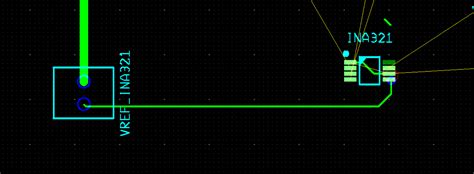
1. Misaligned or Improperly Seated Connectors
One of the most frequent PCB connectivity errors in multi-board systems is misaligned or improperly seated connectors. This issue can arise due to various factors, such as:
- Manufacturing tolerances
- Incorrect connector placement during assembly
- Mechanical stress or vibration during operation
Causes of Misaligned or Improperly Seated Connectors
Manufacturing Tolerances
PCB manufacturers have specific tolerances for the placement of components, including connectors. If these tolerances are not met, the connectors may not align properly when the boards are mated. This misalignment can lead to poor electrical contact or complete failure of the connection.
Incorrect Connector Placement During Assembly
During the assembly process, connectors must be placed accurately on the PCB. If the connectors are not positioned correctly, they may not mate properly with their counterparts on the other board. This issue can be caused by human error or improper assembly equipment settings.
Mechanical Stress or Vibration During Operation
Even if the connectors are initially aligned and seated correctly, mechanical stress or vibration during operation can cause them to become misaligned or dislodged. This is particularly problematic in applications where the multi-board system is subject to high levels of vibration or shock, such as in automotive or aerospace environments.
Prevention Strategies
To prevent misaligned or improperly seated connectors, consider the following strategies:
- Work closely with your PCB manufacturer to ensure that the connectors are placed within the specified tolerances.
- Implement strict quality control measures during the assembly process to verify correct connector placement.
- Use connectors with guide pins or other alignment features to ensure proper mating.
- Incorporate mechanical supports or strain relief mechanisms to minimize stress on the connectors during operation.
2. Insufficient Grounding and Shielding
Another common PCB connectivity error in multi-board systems is insufficient grounding and shielding. Proper grounding and shielding are essential for maintaining signal integrity and reducing electromagnetic interference (EMI) between boards.
Causes of Insufficient Grounding and Shielding
Inadequate Ground Plane Design
The ground plane is a critical component of PCB design, serving as a reference point for electrical signals and providing a low-impedance return path. If the ground plane is not designed properly, with insufficient coverage or improper connections to the connectors, it can lead to signal integrity issues and increased EMI.
Lack of Shielding
In multi-board systems, EMI can be a significant problem, as the signals from one board can interfere with those on another. Shielding is used to contain EMI within a specific area and prevent it from affecting other parts of the system. If shielding is not implemented correctly or is inadequate, EMI can cause signal degradation and other performance issues.
Prevention Strategies
To ensure sufficient grounding and shielding in multi-board PCB systems, consider the following strategies:
- Design a robust ground plane with adequate coverage and proper connections to the connectors.
- Use ground planes on both sides of the PCB, connected through vias, to provide a low-impedance return path.
- Implement shielding techniques, such as metal enclosures or conductive gaskets, to contain EMI.
- Use shielded connectors and cables to minimize EMI between boards.

3. Incorrect Impedance Matching
Impedance matching is crucial for maintaining signal integrity in multi-board PCB systems. When signals travel between boards, they encounter impedance discontinuities at the connectors, which can cause reflections and degrade signal quality. Incorrect impedance matching is a common PCB connectivity error that can lead to signal integrity issues.
Causes of Incorrect Impedance Matching
Improper PCB Stack-up Design
The PCB stack-up, which refers to the arrangement of conductive and insulating layers, plays a significant role in determining the impedance of the traces. If the stack-up is not designed correctly, with the proper dielectric materials and thicknesses, it can result in incorrect impedance matching at the connectors.
Inconsistent Trace Widths and Spacing
Trace width and spacing also affect impedance. If the traces connecting to the connectors have inconsistent widths or spacing, it can cause impedance mismatches, leading to signal reflections and degradation.
Prevention Strategies
To avoid incorrect impedance matching in multi-board PCB systems, consider the following strategies:
- Work with your PCB manufacturer to design a stack-up that achieves the desired impedance for your application.
- Use consistent trace widths and spacing throughout the design, particularly for traces connecting to connectors.
- Simulate the PCB design to verify impedance matching and make adjustments as needed.
- Use impedance-matched connectors and cables to minimize discontinuities between boards.

Frequently Asked Questions (FAQ)
1. What are the most common types of connectors used in multi-board PCB systems?
Some of the most common types of connectors used in multi-board PCB systems include:
- Board-to-board connectors
- Edge connectors
- Mezzanine connectors
- High-speed backplane connectors
2. How can I test for connectivity issues in a multi-board PCB system?
To test for connectivity issues in a multi-board PCB system, you can:
- Perform visual inspections to check for misaligned or improperly seated connectors
- Use a multimeter or continuity tester to verify electrical connections
- Conduct signal integrity tests using an oscilloscope or network analyzer
- Perform functional tests to ensure the system operates as intended
3. What is the impact of PCB connectivity errors on system performance?
PCB connectivity errors can have a significant impact on system performance, including:
- Signal degradation and loss of data integrity
- Intermittent operation or complete system failure
- Increased electromagnetic interference (EMI)
- Reduced reliability and longevity of the system
4. How can I minimize the risk of PCB connectivity errors during the design phase?
To minimize the risk of PCB connectivity errors during the design phase, you should:
- Work closely with your PCB manufacturer to ensure proper design and manufacturing practices
- Use simulation tools to verify signal integrity and impedance matching
- Incorporate design for manufacturability (DFM) principles to ensure the design is compatible with the manufacturing process
- Follow best practices for grounding, shielding, and impedance matching
5. What are the consequences of not addressing PCB connectivity errors in a multi-board system?
Failing to address PCB connectivity errors in a multi-board system can lead to:
- Increased development time and costs due to rework and debugging
- Decreased product reliability and customer satisfaction
- Potential safety hazards, depending on the application
- Damage to the company’s reputation and loss of market share
| Error Type | Causes | Prevention Strategies |
|---|---|---|
| Misaligned or Improperly Seated Connectors | – Manufacturing tolerances – Incorrect connector placement during assembly – Mechanical stress or vibration during operation |
1. Ensure connectors are placed within specified tolerances 2. Implement strict quality control during assembly 3. Use connectors with alignment features 4. Incorporate mechanical supports or strain relief |
| Insufficient Grounding and Shielding | – Inadequate ground plane design – Lack of shielding |
1. Design a robust ground plane 2. Use ground planes on both sides of the PCB 3. Implement shielding techniques 4. Use shielded connectors and cables |
| Incorrect Impedance Matching | – Improper PCB stack-up design – Inconsistent trace widths and spacing |
1. Design stack-up for desired impedance 2. Use consistent trace widths and spacing 3. Simulate PCB design to verify impedance matching 4. Use impedance-matched connectors and cables |
In conclusion, understanding and addressing the top three multi-board PCB connectivity errors – misaligned or improperly seated connectors, insufficient grounding and shielding, and incorrect impedance matching – is essential for ensuring the optimal performance and reliability of your system. By implementing the prevention strategies discussed in this article and working closely with your PCB manufacturer, you can minimize the risk of these errors and develop a robust, high-quality multi-board PCB system.


Leave a Reply