What is a Fabrication Drawing?
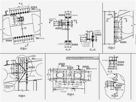
A fabrication drawing, also known as a shop drawing or production drawing, is a detailed technical diagram that provides all the necessary information for manufacturing a product or component. These drawings are essential for communicating the designer’s intent to the fabrication team, ensuring that the final product meets the required specifications and tolerances.
Fabrication drawings typically include:
– Detailed dimensions
– Material specifications
– Tolerances
– Finishing requirements
– Assembly instructions
– Any other relevant information needed for production
The Importance of Fabrication Drawings
Fabrication drawings play a crucial role in the manufacturing process by:
- Reducing errors and misinterpretation
- Ensuring consistency and quality control
- Facilitating communication between design and production teams
- Streamlining the manufacturing process
- Providing a reference for future maintenance and repairs
Creating a Fabrication Drawing in Draftsman
Draftsman is a powerful CAD software that enables users to create detailed and accurate fabrication drawings. In this section, we will guide you through the process of creating a fabrication drawing using Draftsman.
Step 1: Set Up Your Drawing Environment
Before starting your fabrication drawing, it’s essential to set up your drawing environment correctly. This includes:
- Choosing the appropriate template
- Setting the correct units and scale
- Configuring your layers and line types
- Customizing your workspace to suit your needs
Step 2: Create the Basic Geometry
Begin by creating the basic geometry of your component or product. This involves:
- Sketching the primary shapes and features
- Applying constraints and dimensions to define the size and position of elements
- Creating additional features such as holes, slots, or chamfers
- Verifying the geometry for accuracy and completeness
Step 3: Add Detailed Dimensions and Tolerances
Once the basic geometry is complete, add detailed dimensions and tolerances to your fabrication drawing. This step is crucial for ensuring that the manufactured component meets the required specifications.
- Apply dimensions to all critical features
- Specify tolerances for size, position, and form
- Use appropriate dimension styles and formats
- Ensure that dimensions are legible and unambiguous
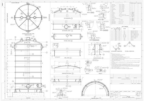
Step 4: Specify Material and Finishing Requirements
Include information about the material and finishing requirements for your component in the fabrication drawing. This may include:
- Material grade and specification
- Surface finish and texture
- Heat treatment or coating requirements
- Any special processing instructions
Step 5: Create Assembly Instructions and Notes
If your fabrication drawing involves multiple components or subassemblies, provide clear assembly instructions and notes. This may include:
- Exploded views or assembly sequences
- Fastener and joining methods
- Torque specifications or assembly tolerances
- Any special assembly techniques or precautions
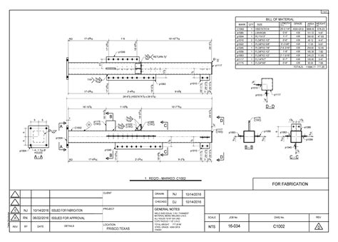
Step 6: Add Title Block and Revision Information
Complete your fabrication drawing by adding a title block and revision information. The title block should include:
- Drawing title and number
- Company name and logo
- Designer and approver names
- Date and revision history
- Any other relevant project information
Step 7: Review and Verify the Drawing
Before releasing your fabrication drawing, thoroughly review and verify all aspects of the drawing. This includes:
- Checking dimensions and tolerances for accuracy
- Ensuring that all necessary information is included
- Verifying that the drawing meets company standards and conventions
- Obtaining approval from the appropriate stakeholders
Best Practices for Creating Fabrication Drawings
To ensure that your fabrication drawings are effective and efficient, follow these best practices:
- Use clear and consistent formatting
- Provide unambiguous and complete information
- Adhere to industry standards and conventions
- Collaborate with fabrication teams to understand their needs
- Regularly review and update drawings to reflect changes or improvements

Common Mistakes to Avoid in Fabrication Drawings
Avoid these common mistakes when creating fabrication drawings:
- Incomplete or missing dimensions
- Ambiguous or conflicting information
- Poor legibility or organization
- Failure to specify critical tolerances or requirements
- Lack of revision control or version history
The Future of Fabrication Drawings
As technology advances, the future of fabrication drawings is evolving. Some trends to watch include:
- Increased use of 3D modeling and visualization
- Integration with computer-aided manufacturing (CAM) systems
- Adoption of digital twin technology for real-time monitoring and optimization
- Implementation of augmented reality (AR) and virtual reality (VR) for immersive design and fabrication experiences
Frequently Asked Questions (FAQ)
1. What is the difference between a fabrication drawing and an engineering drawing?
A fabrication drawing is a type of engineering drawing that focuses specifically on providing the information needed for manufacturing a component or product. Engineering drawings encompass a broader range of technical diagrams, including conceptual designs, assembly drawings, and installation instructions.
2. How detailed should a fabrication drawing be?
A fabrication drawing should be as detailed as necessary to ensure that the component can be manufactured accurately and consistently. This may include specifying tight tolerances, providing comprehensive dimensions, and including any special processing or assembly instructions.
3. Can fabrication drawings be created in 2D or 3D?
Fabrication drawings can be created in both 2D and 3D formats. 2D drawings are more traditional and are often sufficient for simple components or legacy projects. 3D fabrication drawings offer more flexibility, enabling better visualization and integration with modern manufacturing processes.
4. What are the benefits of using Draftsman for creating fabrication drawings?
Draftsman is a powerful and user-friendly CAD software that offers several benefits for creating fabrication drawings, including:
- Comprehensive drawing tools and templates
- Intelligent dimensioning and annotation features
- Built-in material and finishing libraries
- Integration with other design and manufacturing software
5. How can I ensure that my fabrication drawings are easily understood by the production team?
To ensure that your fabrication drawings are easily understood by the production team, follow these guidelines:
- Use clear and consistent formatting and symbology
- Provide complete and unambiguous information
- Organize the drawing logically and use appropriate labels and notes
- Collaborate with the production team to understand their needs and preferences
- Regularly review and update the drawings based on feedback and changes
Conclusion
Creating accurate and comprehensive fabrication drawings is essential for ensuring the success of any manufacturing project. By following the steps and best practices outlined in this article, you can use Draftsman to create high-quality fabrication drawings that effectively communicate your design intent to the production team.
Remember to keep your drawings clear, consistent, and complete, and to collaborate closely with the fabrication team throughout the process. By doing so, you can streamline the manufacturing process, reduce errors and delays, and ultimately deliver a successful product.
Leave a Reply