Introduction to LED PCBs
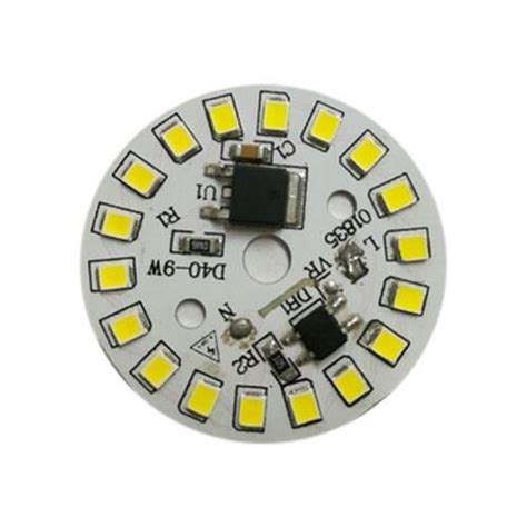
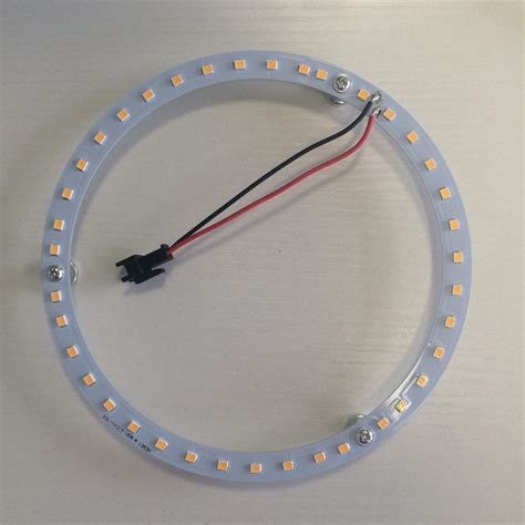
An LED PCB (Light Emitting Diode Printed Circuit Board) is a specialized type of printed circuit board designed specifically for powering and controlling LEDs. LED PCBs are used in a wide range of applications, from simple status indicators to complex lighting systems and displays.
The key features of an LED PCB include:
- Conductive traces to deliver power and control signals to the LEDs
- Pads or through-holes for mounting the LEDs
- Thermal management features to dissipate heat generated by the LEDs
- Additional components such as resistors, capacitors, and drivers to control LED behavior
Advantages of LED PCBs
LED PCBs offer several advantages over traditional wiring methods:
- Compact and space-efficient design
- Improved reliability and durability
- Easier assembly and maintenance
- Better thermal management and heat dissipation
- Precise control over LED placement and orientation
LED PCB Design Considerations
When designing an LED PCB, several factors must be considered to ensure optimal performance and reliability.
LED Selection
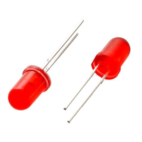
Choosing the right type of LED is crucial for achieving the desired lighting effect and ensuring compatibility with the PCB design. Factors to consider include:
- Color (wavelength)
- Brightness (luminous intensity)
- Forward voltage and current
- Viewing angle
- Package size and shape
PCB Material
The choice of PCB material depends on the specific requirements of the application, such as thermal conductivity, durability, and cost. Common materials used for LED PCBs include:
- FR-4: A standard PCB material with good electrical insulation properties but limited thermal conductivity.
- Metal Core PCB (MCPCB): Features a metal base layer for improved heat dissipation, making it suitable for high-power LED applications.
- Flexible PCB: Made from flexible materials like polyimide, allowing for non-planar designs and improved durability in applications subject to vibration or flexing.
Trace Width and Thickness
The width and thickness of the conductive traces on an LED PCB must be carefully designed to ensure adequate current-carrying capacity and minimize voltage drop. Factors to consider include:
- LED current requirements
- Trace length
- Ambient temperature
- PCB manufacturing capabilities
IPC-2221 provides guidelines for minimum trace width and thickness based on the required current and temperature rise.
Thermal Management
Proper thermal management is essential for ensuring the longevity and performance of LEDs. Strategies for managing heat on an LED PCB include:
- Using a metal core PCB (MCPCB) or other thermally conductive substrate
- Incorporating thermal vias to transfer heat from the LED pads to the opposite side of the board
- Adding heatsinks or other passive cooling solutions
- Using thermal interface materials (TIMs) to improve heat transfer between the LED and PCB
LED Placement and Orientation
The placement and orientation of LEDs on the PCB can significantly impact the overall lighting effect and uniformity. Considerations include:
- Desired beam pattern and viewing angle
- Spacing between LEDs to ensure uniform illumination
- Orientation of the LED package for optimal heat dissipation and light output
- Mechanical constraints and assembly requirements

LED PCB Assembly Process
The assembly process for LED PCBs typically involves the following steps:
-
Solder Paste Application: Solder paste is applied to the pads on the PCB using a stencil or screen printing process.
-
Pick and Place: LED components are placed onto the PCB using automated pick and place equipment or manual assembly methods.
-
Reflow Soldering: The PCB is heated in a reflow oven, melting the solder paste and forming a permanent electrical and mechanical connection between the LEDs and the PCB.
-
Inspection and Testing: The assembled PCB undergoes visual inspection and electrical testing to ensure proper functionality and identify any defects.
-
Cleaning: Residual flux and contaminants are removed from the PCB using cleaning agents or ultrasonic cleaning methods.
-
Conformal Coating (Optional): A protective coating may be applied to the PCB to improve durability and resistance to environmental factors like moisture and corrosion.
LED PCB Soldering Techniques
Two main soldering techniques are used for LED PCB assembly:
-
Reflow Soldering: This is the most common method for LED PCB assembly, involving the application of solder paste and the use of a reflow oven to melt the solder and form a connection. Reflow soldering is well-suited for surface mount LEDs and can be easily automated for high-volume production.
-
Hand Soldering: For low-volume production or prototyping, LEDs may be hand-soldered onto the PCB using a soldering iron. This method is more time-consuming and requires skilled operators to ensure consistent results.

LED PCB Testing and Quality Control
To ensure the reliability and performance of LED PCBs, several testing and quality control measures are employed during and after the assembly process.
In-Circuit Testing (ICT)
In-Circuit Testing involves using specialized test equipment to verify the electrical continuity and component values on the PCB. This helps identify issues like open circuits, short circuits, and incorrect component placement.
Functional Testing
Functional testing involves powering up the LED PCB and verifying that the LEDs illuminate correctly and respond to control signals as intended. This may involve the use of automated test equipment or manual visual inspection.
Burn-In Testing
Burn-in testing involves operating the LED PCB under controlled conditions (e.g., elevated temperature and humidity) for an extended period to identify any early failures or performance degradation. This helps ensure the long-term reliability of the PCB in its intended application.
Quality Control Standards
Several industry standards and guidelines are used to ensure the quality and reliability of LED PCBs, including:
- IPC-A-610: Acceptability of Electronic Assemblies
- IPC-6012: Qualification and Performance Specification for Rigid Printed Boards
- IPC-HDBK-830: Guidelines for Design, Selection and Application of Conformal Coatings
- MIL-STD-883: Test Method Standard for Microcircuits
Adherence to these standards helps ensure consistent quality and reliability across different manufacturers and applications.

LED PCB Applications
LED PCBs find use in a wide range of applications, from general lighting to specialized displays and indicators.
General Lighting
LED PCBs are widely used in general lighting applications, such as:
- Indoor and outdoor lighting fixtures
- Retrofit lamps and bulbs
- Architectural lighting
- Automotive lighting
The use of LED PCBs in these applications offers benefits like improved energy efficiency, longer lifespan, and greater design flexibility compared to traditional lighting technologies.
Backlighting
LED PCBs are commonly used for backlighting applications in displays and signage, such as:
- LCD displays (e.g., televisions, monitors, mobile devices)
- Advertising billboards and signs
- Instrument panels and gauges
- Keypads and buttons
LED PCBs enable thin, uniform, and efficient backlighting solutions for these applications.
Indicators and Status Lights
LED PCBs are used for various indicator and status light applications, such as:
- Power indicators on electronic devices
- Network status indicators on routers and switches
- Fault indicators on industrial equipment
- Traffic signals and warning lights
The use of LED PCBs allows for compact, reliable, and energy-efficient indicator solutions.
Specialized Lighting
LED PCBs are also used in various specialized lighting applications, such as:
- Grow lights for indoor farming and horticulture
- Medical and dental lighting
- UV curing and disinfection systems
- Machine vision and inspection lighting
The specific requirements of these applications, such as wavelength, intensity, and beam pattern, can be easily met using custom LED PCB designs.
Advantages of LED PCBs
LED PCBs offer several advantages over traditional lighting and display solutions:
-
Energy Efficiency: LEDs are highly energy-efficient compared to traditional lighting sources like incandescent and fluorescent lamps, resulting in lower power consumption and operating costs.
-
Long Lifespan: LED PCBs have a significantly longer lifespan than traditional lighting solutions, with many LEDs rated for 50,000 hours or more of continuous use. This reduces maintenance and replacement costs.
-
Design Flexibility: LED PCBs can be custom-designed to meet specific size, shape, and performance requirements, enabling greater design flexibility for lighting and display applications.
-
Durability: LED PCBs are solid-state devices with no moving parts or fragile components, making them highly resistant to shock, vibration, and environmental factors like temperature and humidity.
-
Color Control: LEDs are available in a wide range of colors, and their output can be easily controlled and mixed to achieve specific color temperatures and effects.
-
Instant On/Off: LEDs have fast response times and can be instantly switched on and off, making them well-suited for applications requiring precise control and dynamic lighting effects.
-
Eco-Friendly: LEDs contain no toxic materials like mercury, making them a more environmentally friendly lighting solution compared to fluorescent lamps.
Challenges and Limitations of LED PCBs
While LED PCBs offer many advantages, there are also some challenges and limitations to consider:
-
Heat Management: LEDs generate significant amounts of heat, which must be effectively dissipated to ensure optimal performance and longevity. This requires careful PCB design and the use of thermal management strategies like metal core PCBs and heatsinks.
-
Initial Cost: The initial cost of LED PCBs can be higher than traditional lighting solutions due to the cost of the LEDs themselves and the specialized manufacturing processes required.
-
Driver Complexity: LEDs require precise current and voltage control to operate effectively, which necessitates the use of specialized driver circuits. This can add complexity and cost to the overall system design.
-
Color Consistency: Ensuring consistent color output across multiple LEDs can be challenging due to variations in LED binning and manufacturing processes. This may require additional calibration and color management techniques.
-
Limited High-Temperature Performance: While LEDs are generally tolerant of high temperatures, their performance and lifespan can be negatively affected by extreme heat. This may limit their use in certain high-temperature applications.
Despite these challenges, the benefits of LED PCBs continue to drive their adoption across a wide range of industries and applications.
Future Trends in LED PCB Technology
As LED technology continues to advance, several trends are shaping the future of LED PCBs:
-
Miniaturization: Advances in LED packaging and PCB manufacturing are enabling the development of increasingly small and compact LED PCBs, opening up new possibilities for integrated lighting solutions.
-
Flexible and Stretchable PCBs: The development of flexible and stretchable PCB materials is enabling new applications for LED PCBs, such as wearable devices and conformable lighting installations.
-
Smart Lighting: The integration of LED PCBs with sensors, wireless connectivity, and control systems is enabling the development of smart lighting solutions that can adapt to user preferences and environmental conditions.
-
UV and IR LEDs: The development of high-power UV and IR LEDs is opening up new applications for LED PCBs in areas like disinfection, curing, and sensing.
-
Sustainable Manufacturing: There is a growing focus on sustainable manufacturing practices for LED PCBs, including the use of eco-friendly materials, reduced waste generation, and improved energy efficiency in production processes.
As these trends continue to shape the LED PCB industry, we can expect to see further innovations and advancements in the years to come.
FAQ
1. What is the difference between an LED PCB and a regular PCB?
An LED PCB is specifically designed to power and control LEDs, while a regular PCB is a general-purpose board used for a wide range of electronic applications. LED PCBs often incorporate specialized features like thermal management and precise current control to ensure optimal LED performance.
2. Can I use a regular PCB for my LED project?
While it is possible to use a regular PCB for an LED project, it may not provide the optimal performance and reliability. LED PCBs are designed with specific considerations in mind, such as thermal management and current control, which are essential for ensuring the longevity and efficiency of LEDs.
3. What are the most common materials used for LED PCBs?
The most common materials used for LED PCBs are:
- FR-4: A standard PCB material with good electrical insulation properties but limited thermal conductivity.
- Metal Core PCB (MCPCB): Features a metal base layer for improved heat dissipation, making it suitable for high-power LED applications.
- Flexible PCB: Made from flexible materials like polyimide, allowing for non-planar designs and improved durability.
4. How do I choose the right LED for my PCB design?
When choosing an LED for your PCB design, consider factors such as:
- Color (wavelength)
- Brightness (luminous intensity)
- Forward voltage and current
- Viewing angle
- Package size and shape
Ensure that the chosen LED is compatible with your PCB design and meets the specific requirements of your application.
5. What are some common applications for LED PCBs?
LED PCBs are used in a wide range of applications, including:
- General lighting (indoor and outdoor fixtures, retrofit lamps, automotive lighting)
- Backlighting (LCD displays, signage, instrument panels)
- Indicators and status lights (power indicators, network status lights, fault indicators)
- Specialized lighting (grow lights, medical lighting, UV curing, machine vision)
The versatility and benefits of LED PCBs make them a popular choice across various industries and applications.

Leave a Reply