
Introduction to Star-Ground Techniques
In electronics design, proper grounding is crucial for ensuring the stability, performance, and reliability of a system. One of the most effective grounding techniques is the star-ground approach, which involves connecting all ground points to a single, central point known as the star point. This method is particularly useful when dealing with mixed-signal systems that incorporate both analog and digital circuitry.
In this article, we will explore the concept of star-ground, its benefits, and how to implement it effectively in your designs. We will also discuss the importance of separating analog and digital grounds and how to use a star point to achieve optimal ground connection.
Understanding the Importance of Proper Grounding
Grounding plays a vital role in electronic systems by providing a reference point for voltage measurements and a path for currents to return to their source. Improper grounding can lead to various issues, such as:
- Noise and interference: Poor grounding can allow noise and interference to couple into sensitive circuits, degrading signal integrity and overall system performance.
- Ground loops: When multiple ground points are connected in a loop, ground currents can flow through the loop, causing voltage differences and introducing noise.
- Electromagnetic interference (EMI): Inadequate grounding can make a system more susceptible to EMI, both in terms of emissions and susceptibility.
To mitigate these issues, it is essential to implement a well-designed grounding scheme, and the star-ground technique is one of the most effective approaches.

The Star-Ground Concept
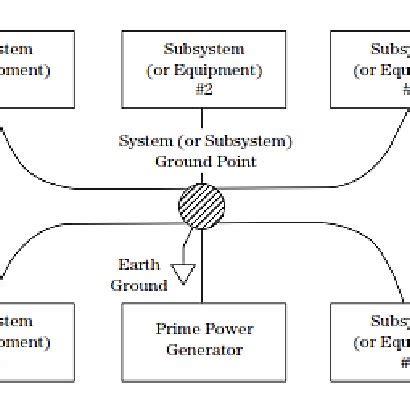
The star-ground technique involves connecting all ground points in a system to a single, central point, forming a star-like pattern. This central point is often referred to as the star point or star node. By using a star-ground configuration, you can minimize the ground impedance and reduce the potential for ground loops and noise coupling.
Here are some key benefits of using a star-ground:
-
Reduced ground impedance: By connecting all ground points to a single node, the star-ground minimizes the overall ground impedance, ensuring a low-impedance path for ground currents.
-
Minimized ground loops: The star-ground configuration eliminates ground loops by preventing multiple paths for ground currents to flow, thus reducing noise and interference.
-
Improved signal integrity: With a star-ground, sensitive analog and digital signals have a clean, low-impedance reference point, resulting in better signal quality and reduced crosstalk.
-
Enhanced EMI performance: A well-implemented star-ground can help reduce EMI emissions and improve the system’s immunity to external EMI sources.

Separating Analog and Digital Grounds
In mixed-signal systems, it is crucial to separate analog and digital grounds to prevent noise coupling between the two domains. Digital circuits, with their fast switching and high-frequency components, can generate significant noise that can easily couple into sensitive analog circuits if not properly isolated.
To achieve effective separation, you should:
- Physically separate analog and digital circuits on the PCB layout.
- Use separate ground planes for analog and digital sections.
- Connect the analog and digital ground planes at a single point, typically near the power supply or the ADC/DAC interface.
By separating the analog and digital grounds and connecting them at a single point, you can minimize noise coupling and ensure a clean reference for both domains.
Implementing a Star-Ground
To implement a star-ground in your design, follow these steps:
-
Identify the central star point: Choose a location for the star point, typically near the power supply or the most sensitive component in your system (e.g., an ADC or DAC).
-
Route ground connections to the star point: Connect all ground points in your system to the central star point using low-impedance paths, such as wide traces or ground planes.
-
Use separate ground planes: If your design includes both analog and digital sections, use separate ground planes for each domain and connect them at the star point.
-
Minimize trace lengths: Keep the ground traces as short as possible to reduce impedance and minimize the potential for noise coupling.
-
Avoid daisy-chaining ground connections: Do not connect ground points in a daisy-chain fashion, as this can create ground loops and increase ground impedance.
Here’s an example of how to implement a star-ground in a mixed-signal system:
         Power Supply
              |
              |
         Star Point
          /      \
         /        \
 Analog Ground  Digital Ground
        |             |
        |             |
 Analog Circuits  Digital Circuits
In this example, the star point is located near the power supply, and the analog and digital grounds are connected to the star point using separate paths. This configuration ensures a low-impedance ground connection and minimizes noise coupling between the analog and digital domains.
Best Practices for Star-Ground Implementation
To ensure the effectiveness of your star-ground implementation, consider the following best practices:
-
Use low-impedance connections: Ensure that all ground connections to the star point have low impedance by using wide traces, ground planes, or multiple vias.
-
Place the star point strategically: Position the star point close to the most sensitive components or the interface between analog and digital sections to minimize noise coupling.
-
Avoid ground loops: Carefully review your design to identify and eliminate any potential ground loops that could compromise the star-ground configuration.
-
Use ground planes: Implement ground planes whenever possible to provide a low-impedance return path for ground currents and to minimize noise coupling.
-
Decouple power supplies: Use appropriate decoupling capacitors near power supply pins to reduce high-frequency noise and ensure a stable reference for the star-ground.
By following these best practices, you can ensure that your star-ground implementation is effective and provides the desired benefits for your mixed-signal system.
Example: Star-Ground in a Data Acquisition System
To illustrate the application of a star-ground, let’s consider a data acquisition system that includes an analog sensor, an amplifier, an analog-to-digital converter (ADC), and a microcontroller.
         Power Supply
              |
              |
         Star Point
          /      \
         /        \
 Analog Ground  Digital Ground
        |             |
        |             |
  Sensor & Amplifier  ADC & Microcontroller
In this example, the star point is located near the power supply, and the analog and digital grounds are separated. The sensor and amplifier are connected to the analog ground, while the ADC and microcontroller are connected to the digital ground. The analog and digital grounds are connected only at the star point, minimizing noise coupling between the two domains.
By implementing a star-ground in this data acquisition system, you can ensure that the sensitive analog signals from the sensor and amplifier are not corrupted by digital noise from the ADC and microcontroller. This results in improved signal integrity and overall system performance.
Troubleshooting Star-Ground Issues
If you encounter issues with your star-ground implementation, consider the following troubleshooting steps:
-
Check for ground loops: Carefully review your design and PCB layout to identify any unintended ground loops that could be causing noise or interference.
-
Verify low-impedance connections: Ensure that all ground connections to the star point have low impedance by measuring the resistance between the ground points and the star point.
-
Inspect the PCB layout: Look for any layout issues that could be compromising the star-ground, such as long ground traces or insufficient spacing between analog and digital sections.
-
Analyze noise levels: Use an oscilloscope or spectrum analyzer to measure noise levels at various points in your system, and compare them to expected values to identify any anomalies.
-
Review decoupling: Verify that your power supplies are properly decoupled and that the decoupling capacitors are placed close to the relevant components.
By systematically troubleshooting your star-ground implementation, you can identify and resolve any issues affecting your system’s performance.
Conclusion
Implementing a star-ground is an effective way to ensure proper grounding in mixed-signal systems, minimizing noise coupling and improving overall system performance. By connecting all ground points to a single, central star point and separating analog and digital grounds, you can create a low-impedance, noise-resistant grounding scheme.
When designing your star-ground, remember to follow best practices such as using low-impedance connections, placing the star point strategically, avoiding ground loops, and using ground planes whenever possible. If you encounter issues, systematically troubleshoot your design by checking for ground loops, verifying low-impedance connections, inspecting the PCB layout, analyzing noise levels, and reviewing decoupling.
By understanding and applying the principles of star-ground, you can create robust, reliable, and high-performance electronic systems that meet the demands of today’s complex applications.
Frequently Asked Questions (FAQ)
-
What is a star-ground, and why is it important?
A star-ground is a grounding technique where all ground points in a system are connected to a single, central point called the star point. It is important because it minimizes ground impedance, reduces ground loops, improves signal integrity, and enhances EMI performance. -
How does a star-ground differ from other grounding techniques?
Unlike other grounding techniques, such as daisy-chaining or multi-point grounding, a star-ground connects all ground points to a single node, creating a low-impedance, noise-resistant grounding scheme. This approach minimizes ground loops and noise coupling, making it particularly suitable for mixed-signal systems. -
What are the benefits of separating analog and digital grounds?
Separating analog and digital grounds helps prevent noise coupling between the two domains. Digital circuits can generate significant noise that can corrupt sensitive analog signals if not properly isolated. By separating the grounds and connecting them only at the star point, you can minimize noise coupling and ensure a clean reference for both analog and digital circuits. -
How do I choose the location for the star point in my design?
The star point should be located near the most sensitive component in your system, such as an ADC or DAC, or near the power supply. This placement helps minimize noise coupling and ensures a low-impedance ground connection for the sensitive components. -
What should I do if I encounter issues with my star-ground implementation?
If you encounter issues with your star-ground implementation, you should systematically troubleshoot your design. Check for ground loops, verify low-impedance connections, inspect the PCB layout, analyze noise levels, and review decoupling. By identifying and resolving any issues, you can ensure that your star-ground is functioning effectively and providing the desired benefits for your system.
Leave a Reply