Introduction to 3D-Printed PCBs
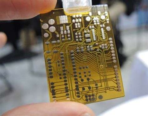
3D printing technology has revolutionized the way we manufacture products, and its applications have expanded to various industries, including electronics. One of the most exciting developments in this field is the ability to 3D print Printed Circuit Boards (PCBs). 3D-printed PCBs offer several advantages over traditional PCB manufacturing methods, such as rapid prototyping, cost-effectiveness, and design flexibility.
What are PCBs?
PCBs are the backbone of modern electronics. They are thin boards made of insulating materials, such as fiberglass or plastic, with conductive tracks, pads, and other features etched onto their surface. These boards provide mechanical support and electrical connectivity for electronic components, such as resistors, capacitors, and integrated circuits (ICs).
Traditional PCB Manufacturing Methods
Conventionally, PCBs are manufactured using a subtractive process, which involves the following steps:
- Designing the PCB layout using CAD software
- Printing the design onto a photoresist film
- Laminating the photoresist film onto a copper-clad board
- Exposing the board to UV light through the photoresist film
- Developing the photoresist to reveal the copper traces
- Etching away the unwanted copper using a chemical solution
- Drilling holes for through-hole components
- Applying a solder mask and silkscreen for protection and labeling
This process is time-consuming, requires specialized equipment, and generates waste materials, such as copper and chemical etchants.
Advantages of 3D-Printed PCBs
3D printing technology offers a new approach to PCB manufacturing that addresses some of the limitations of traditional methods. The main advantages of 3D-printed PCBs include:
- Rapid prototyping: 3D printing allows for quick and easy creation of PCB prototypes, enabling faster iteration and testing of designs.
- Cost-effectiveness: 3D printing eliminates the need for expensive tooling and setup costs associated with traditional PCB manufacturing, making it more affordable for small-scale production and prototyping.
- Design flexibility: 3D printing enables the creation of complex geometries and non-planar PCBs, which are difficult or impossible to achieve with traditional methods.
- Environmentally friendly: 3D printing is an additive process that generates less waste compared to subtractive PCB manufacturing methods.
3D Printing Technologies for PCBs
Several 3D printing technologies have been adapted for PCB manufacturing, each with its own advantages and limitations.
Fused Deposition Modeling (FDM)
FDM is the most common and affordable 3D printing technology. It works by extruding a thermoplastic filament through a heated nozzle, which deposits the molten material layer by layer onto a build platform. For PCB printing, conductive filaments containing metal particles, such as copper or silver, are used alongside standard insulating filaments.
Advantages:
– Low cost and widely available
– Easy to use and maintain
– Compatible with a wide range of materials
Limitations:
– Lower resolution and surface finish compared to other 3D printing technologies
– Limited conductivity of printed traces
– Requires post-processing to improve electrical properties
Stereolithography (SLA)
SLA is a high-resolution 3D printing technology that uses a laser to cure and harden a photopolymer resin layer by layer. For PCB printing, the resin is mixed with conductive particles, such as silver nanoparticles, to create conductive traces.
Advantages:
– High resolution and smooth surface finish
– Faster printing speed compared to FDM
– Good mechanical properties
Limitations:
– More expensive than FDM
– Limited material options
– Requires post-processing to remove support structures and improve conductivity
Selective Laser Sintering (SLS)
SLS is a powder-based 3D printing technology that uses a laser to sinter and fuse powdered materials, such as nylon or metal, layer by layer. For PCB printing, a mixture of polymer and conductive particles is used to create the insulating substrate and conductive traces.
Advantages:
– High mechanical strength and durability
– Good thermal and chemical resistance
– No need for support structures
Limitations:
– Expensive equipment and materials
– Limited resolution compared to SLA
– Requires post-processing to remove excess powder and improve conductivity
Inkjet Printing
Inkjet printing is a 2D printing technology that has been adapted for 3D PCB printing. It works by selectively depositing conductive and insulating inks onto a substrate, building up the PCB layer by layer.
Advantages:
– High precision and resolution
– Multi-material printing capabilities
– Scalable for mass production
Limitations:
– Requires specialized inkjet printheads and inks
– Limited build volume
– Requires post-processing to sinter and cure the inks

Generating 3D Printing Models for PCBs
To 3D print a PCB, you first need to create a 3D model of the board that includes both the insulating substrate and the conductive traces. This process involves the following steps:
-
PCB Design: Design your PCB layout using CAD software, such as KiCad, Eagle, or Altium Designer. Make sure to consider the limitations of your chosen 3D printing technology, such as minimum trace width and spacing.
-
3D Modeling: Convert your PCB design into a 3D model using a 3D modeling software, such as Fusion 360, SolidWorks, or Blender. Create separate models for the insulating substrate and the conductive traces, ensuring that they mate properly.
-
Slicing: Use a slicing software, such as Cura or Slic3r, to generate the G-code for your 3D printer. Set the appropriate print settings, such as layer height, infill density, and print speed, based on your chosen 3D printing technology and materials.
-
Printing: Load the G-code into your 3D printer and start the printing process. Depending on your chosen technology, you may need to print the insulating substrate and conductive traces separately and assemble them afterward.
-
Post-Processing: After printing, you may need to perform some post-processing steps to improve the electrical properties of your PCB. This can include sintering, electroplating, or applying a conductive coating to the traces.
| Step | Software | Description |
|---|---|---|
| PCB Design | KiCad, Eagle, Altium Designer | Design the PCB layout considering 3D printing limitations |
| 3D Modeling | Fusion 360, SolidWorks, Blender | Convert PCB design into 3D models for insulating substrate and conductive traces |
| Slicing | Cura, Slic3r | Generate G-code for 3D printer based on chosen technology and materials |
| Printing | – | Print the insulating substrate and conductive traces separately or together |
| Post-Processing | – | Improve electrical properties through sintering, electroplating, or applying conductive coatings |

Applications and Future Prospects
3D-printed PCBs have numerous applications across various industries, including:
-
Rapid Prototyping: 3D printing enables quick and cost-effective prototyping of PCBs for testing and validation purposes, reducing development time and costs.
-
Customization: 3D printing allows for the creation of highly customized PCBs with unique shapes, sizes, and features, catering to specific application requirements.
-
Aerospace and Defense: 3D-printed PCBs can be used to create lightweight and compact electronic systems for aerospace and defense applications, where space and weight are critical factors.
-
Wearable Electronics: 3D printing enables the integration of electronic circuits into wearable devices, such as smartwatches, fitness trackers, and medical monitoring systems.
-
Internet of Things (IoT): 3D-printed PCBs can be used to create small-scale, low-cost electronic devices for IoT applications, such as sensors, actuators, and communication modules.
As 3D printing technology continues to advance, we can expect to see further improvements in the resolution, conductivity, and multi-material capabilities of 3D-printed PCBs. This will open up new possibilities for electronic device design and manufacturing, leading to more innovative and efficient products.

Frequently Asked Questions (FAQ)
-
What are the most common materials used for 3D printing PCBs?
The most common materials used for 3D printing PCBs are thermoplastics, such as PLA and ABS, mixed with conductive particles, such as copper, silver, or graphene. Photopolymer resins and powdered materials, such as nylon and metal, are also used in some 3D printing technologies. -
Can 3D-printed PCBs replace traditional PCBs?
Currently, 3D-printed PCBs are not a complete replacement for traditional PCBs, especially in high-volume production and applications that require high electrical performance. However, they offer significant advantages in rapid prototyping, customization, and low-volume production, making them a valuable complement to traditional PCB manufacturing methods. -
What is the resolution and minimum feature size of 3D-printed PCBs?
The resolution and minimum feature size of 3D-printed PCBs vary depending on the 3D printing technology used. FDM typically has a resolution of around 100-200 microns, while SLA and inkjet printing can achieve resolutions of 25-50 microns. The minimum feature size, such as trace width and spacing, is typically larger than that of traditional PCBs due to the limitations of 3D printing technologies. -
How do the electrical properties of 3D-printed PCBs compare to traditional PCBs?
The electrical properties of 3D-printed PCBs, such as conductivity and dielectric strength, are generally lower than those of traditional PCBs. This is due to the limitations of conductive materials used in 3D printing and the presence of voids and imperfections in the printed structures. However, post-processing techniques, such as sintering and electroplating, can significantly improve the electrical properties of 3D-printed PCBs. -
Are there any safety concerns associated with 3D printing PCBs?
When 3D printing PCBs, it is essential to follow proper safety guidelines, as some materials and processes may pose health risks. For example, conductive particles and resins may be toxic or cause skin irritation, and the 3D printing process may release fumes or particulates that can be harmful if inhaled. Always work in a well-ventilated area, wear appropriate personal protective equipment (PPE), and follow the manufacturer’s safety instructions when handling 3D printing materials and equipment.
Conclusion
3D printing technology has opened up new possibilities for PCB manufacturing, enabling rapid prototyping, customization, and cost-effective low-volume production. While 3D-printed PCBs currently have limitations in terms of resolution, conductivity, and scalability compared to traditional PCBs, ongoing research and development efforts are continually pushing the boundaries of what is possible.
As 3D printing technologies and materials continue to improve, we can expect to see an increasing adoption of 3D-printed PCBs across various industries, from consumer electronics to aerospace and beyond. By embracing this innovative manufacturing approach, designers and engineers can unlock new opportunities for creating more efficient, customized, and sustainable electronic devices.

Leave a Reply